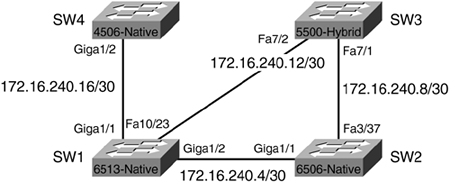
Connecting the Switches
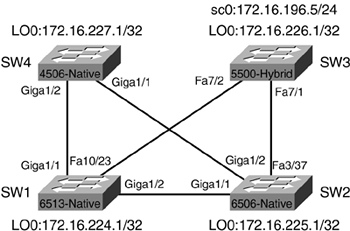
Now that a good portion of the "housekeeping" configuration items are complete, connections between the four switches in Figure 7-4 can be configured. All the physical connections between the switches are already in place.
Figure 7-4. Physical Links Between Switches
IOS Port/Interface Types
Because a combination of platforms is being used in the examples throughout this chapter, it is important to understand the different types of port/interface types that can be configured on a switch running IOS. Table 7-5 outlines the types of port/interfaces and their uses.
Port/Interface Type | Function | Sample Configuration |
|---|---|---|
Routed Physical Interface | Traditional Cisco IOS routed interface. Each interface represents a unique Layer 3 network. | interface gigabitethernet 1/1 no switchport ip address 172.16.100.1 255.255.255.0 |
Routed Switch Virtual Interface (SVI) | Single routed interface for all the switchports assigned to a VLAN. | interface vlan 901 ip address 172.16.200.1 255.255.255.0 |
Access Switch-Port Interface | To group a range of Layer 2 ports into a single VLAN. | interface range fastethernet 2/1-48 switchport mode access switchport access vlan 130 |
Configuring the Connections
The first connection to bring up is the Gigabit connection between SW1 and SW2. This connection is a single Gigabit link and will not be configured as a trunk, but as a routed physical interface. All interfaces on Catalyst 6000/6500s running native IOS default to routed physical interfaces.
In Example 7-20, the current configuration of the GigabitEthernet1/2 interface shows the interface is shut down and no IP address is assigned. In Example 7-20, a /30 IP address is assigned from the range for point-to-point links defined in Table 7-3, earlier in this chapter.
Example 7-20. Configuring the GigabitEthernet Link on SW1
SW1#show run interface gigabitethernet 1/2

Building configuration...


Current configuration : 61 bytes

!

interface GigabitEthernet1/2

 no ip address

 shutdown

end


SW1#config t

Enter configuration commands, one per line.  End with CNTL/Z.

SW1(config)#interface gigabitethernet 1/2

SW1(config-if)#ip address 172.16.240.5 255.255.255.252

SW1(config-if)#no shutdown

SW1(config-if)#end

SW1#
In Example 7-21, the GigabitEthernet interface on SW2 is configured.
Example 7-21. Configuring the GigabitEthernet Link on SW2
SW2#show run interface gig

SW2#show run interface gigabitethernet 1/1

Building configuration...


Current configuration : 61 bytes

!

interface GigabitEthernet1/1

 no ip address

 shutdown

end


SW2#config t

Enter configuration commands, one per line.  End with CNTL/Z.

SW2(config)#interface GigabitEthernet1/1

SW2(config-if)#ip address 172.16.240.6 255.255.255.252

SW2(config-if)#no shut

SW2(config-if)#end

SW2#

1w6d: %SYS-5-CONFIG_I: Configured from console by console
In Example 7-22, a show interface gigabitethernet1/1 command is issued to determine if the interface is now UP/UP, and a ping command is issued to the IP address of the GigabitEthernet1/2 interface on SW1 to determine success.
Example 7-22. Testing the Connection Between SW1 and SW2
SW2#show interface gigabitethernet 1/1

GigabitEthernet1/1 is up, line protocol is up

  Hardware is C6k 1000Mb 802.3, address is 0001.6471.d968 (bia 0001.6471.d968)

  Internet address is 172.16.240.6/30

!output truncated


SW2#ping 172.16.240.5


Type escape sequence to abort.

Sending 5, 100-byte ICMP Echos to 172.16.240.5, timeout is 2 seconds:

!!!!!

Success rate is 100 percent (5/5), round-trip min/avg/max = 1/1/1 ms

SW2#
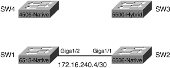
Figure 7-5 shows the network as it is configured at this stage, and the IP addressing information assigned thus far.
Figure 7-5. Link Operational Between SW1 and SW2
Next, the connection between SW2 and SW3 is configured, as shown in Example 7-23.
Example 7-23. Configuring the Connection on SW2 to SW3
SW2#config t

Enter configuration commands, one per line.  End with CNTL/Z.

SW2(config)#interface fastEthernet 3/37

SW2(config-if)#ip address 172.16.240.9 255.255.255.252

SW2(config-if)#no shutdown

SW2(config-if)#end

SW2#
Because SW3 is running hybrid software, the Layer 2 connection in Catalyst OS is configured first, and then the switched virtual interface (SVI) on the RSM is configured. VLAN 901 is selected from the range of VLANs allocated to point-to-point Layer 2 links. Example 7-24 shows VLAN 901 being created and port 7/1 assigned to VLAN 901. The next step is to configure the RSM with a VLAN 901 interface.
Example 7-24. Configuring the Connection on SW3 to SW2 (Catalyst OS)
SW3> (enable) set vlan 901

Vlan 901 configuration successful

SW3> (enable) set vlan 901 7/1

VLAN 901 modified.

VLAN 1 modified.

VLAN  Mod/Ports

---- -----------------------

901   7/1


SW3> (enable)

SW3> (enable) show port 7/1

Port  Name               Status     Vlan       Level  Duplex Speed Type

----- ------------------ ---------- ---------- ------ ------ ----- ------------

 7/1                     connected  901        normal a-full a-100 10/100BaseTX

!Output truncated

SW3> (enable)
Example 7-25 shows VLAN 901 being configured on the RSM of SW3.
Example 7-25. Configuring VLAN 901 on the RSM on SW3
RSM1>en

RSM1#config t

Enter configuration commands, one per line.  End with CNTL/Z.

RSM1(config)#interface vlan901

RSM1(config-if)#ip address 172.16.240.10 255.255.255.252

RSM1(config-if)#no shut

RSM1(config-if)#end

RSM1#
In Example 7-26, the show interface vlan901 command is issued to determine if the interface is now UP/UP, and a ping is issued to the IP address of the FastEthernet3/37 interface on SW2 to determine success.
Example 7-26. Testing the Connection Between SW3 and SW2
RSM1#show interface vlan901

Vlan901 is up, line protocol is up

  Hardware is Cat5k Virtual Ethernet, address is 0010.f6b3.4800 (bia 0010.f6

800)

  Internet address is 172.16.240.10/30

!output truncated


RSM1#ping 172.16.240.9


Type escape sequence to abort.

Sending 5, 100-byte ICMP Echos to 172.16.240.9, timeout is 2 seconds:

!!!!!

Success rate is 100 percent (5/5), round-trip min/avg/max = 1/9/40 ms

RSM1#
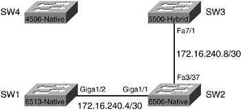
Figure 7-6 shows the network as it looks at this stage, and the IP addressing information assigned thus far.
Figure 7-6. Link Operational Between SW3 and SW2
Next, the connection between SW3 and SW1 is configured (see Example 7-27). Again, the Layer 2 connection in Catalyst OS is configured first, followed by the SVI on the RSM. VLAN 902 is used for this link.
Example 7-27. Configuring the Connection on SW3 to SW1 (Catalyst OS)
SW3> (enable) set vlan 902

Vlan 902 configuration successful

SW3> (enable) set vlan 902 7/2

VLAN 902 modified.

VLAN 1 modified.

VLAN  Mod/Ports

---- -----------------------

902   7/2


SW3> (enable) show port 7/2

Port  Name               Status     Vlan       Level  Duplex Speed Type

----- ------------------ ---------- ---------- ------ ------ ----- ------------

 7/2                     connected  902        normal a-full a-100 10/100BaseTX

!output truncated
The next step is to configure the RSM with a VLAN902 interface, as shown in Example 7-28.
Example 7-28. Configuring VLAN902 on the RSM on SW3
RSM1#config t

Enter configuration commands, one per line.  End with CNTL/Z.

RSM1(config)#interface VLAN902

RSM1(config-if)#ip address 172.16.240.13 255.255.255.252

RSM1(config-if)#no shutdown

RSM1(config-if)#end
Now that the SW3 side of the connection is configured, the other side is configured on SW1 (see Example 7-29).
Example 7-29. Configuring the Connection Between SW1 and SW3
SW1#show run interface FastEthernet10/23

Building configuration...


Current configuration : 60 bytes

!

interface FastEthernet10/23

 no ip address

 shutdown

end


SW1#config t

Enter configuration commands, one per line.  End with CNTL/Z.

SW1(config)#interface FastEthernet10/23

SW1(config-if)#ip address 172.16.240.14 255.255.255.252

SW1(config-if)#no shutdown

SW1(config-if)#end

SW1#
In Example 7-30, a show interface FastEthernet10/23 command is issued to determine if the interface is now UP/UP, and a ping is issued to the IP address of the VLAN902 interface on SW3 to determine success.
Example 7-30. Testing the Connection Between SW1 and SW3
SW1#show interface FastEthernet10/23

FastEthernet10/23 is up, line protocol is up

  Hardware is C6k 100Mb 802.3, address is 0005.7418.048a (bia 0005.7418.048a)

  Internet address is 172.16.240.14/30

!output truncated


SW1#ping 172.16.240.13


Type escape sequence to abort.

Sending 5, 100-byte ICMP Echos to 172.16.240.13, timeout is 2 seconds:

!!!!!

Success rate is 100 percent (5/5), round-trip min/avg/max = 1/1/4 ms

SW1#
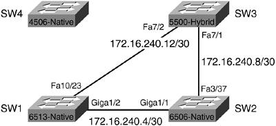
Figure 7-7 shows the network as it looks at this stage, and the IP addressing information assigned thus far.
Figure 7-7. Link Operational Between SW3 and SW1
Next, the connection between SW1 and SW4 is configured, as shown in Example 7-31.
Example 7-31. Configuring the Connection on SW1 to SW4
SW1#show run interface gigabitethernet 1/1

Building configuration...


Current configuration : 61 bytes

!

interface GigabitEthernet1/1

 no ip address

 shutdown

end


SW1#config t

Enter configuration commands, one per line.  End with CNTL/Z.

SW1(config)#interface gigabitethernet 1/1

SW1(config-if)#ip address 172.16.240.17 255.255.255.252

SW1(config-if)#no shutdown

SW1(config-if)#end

SW1#
Next, the connection between SW1 and SW4 is configured, as shown in Example 7-32.
Example 7-32. Configuring the Connection on SW4 to SW1
SW4#show run interface gigabitethernet 1/2

Building configuration...


Current configuration : 36 bytes

!

interface GigabitEthernet1/2

end


SW4#config t

Enter configuration commands, one per line.  End with CNTL/Z.

SW4(config)#interface gigabitethernet 1/2

SW4(config-if)#no switchport

SW4(config-if)#ip address 172.16.240.18 255.255.255.252

SW4(config-if)#end

SW4#
It is important to understand that the Catalyst 4500 series switch defaults to all interfaces being configured as Access Port Switch Interfaces. To convert the gigabitethernet1/2 interface from a Layer 2 switchport to a Layer 3 routed physical interface, the no switchport command must be used prior to assigning the IP address in Example 7-32.
In Example 7-33, the show interface gigabitethernet1/2 command is issued to determine if the interface is now up/up and a ping is issued to the IP address of the GigabitEthernet 1/1 interface on SW1 to determine success.
Figure 7-8 shows the network as it looks at this stage, and the IP addressing information assigned thus far.
Example 7-33. Testing the Connection Between SW4 and SW1
SW4#show interface gigabitethernet 1/2

GigabitEthernet1/2 is up, line protocol is up (connected)

  Hardware is Gigabit Ethernet Port, address is 000b.fdd5.62bf (bia 000b.fdd5

bf)

  Internet address is 172.16.240.18/30

!output truncated


SW4#ping 172.16.240.17


Type escape sequence to abort.

Sending 5, 100-byte ICMP Echos to 172.16.240.17, timeout is 2 seconds:

!!!!!

Success rate is 100 percent (5/5), round-trip min/avg/max = 4/4/4 ms

SW4#
Figure 7-8. Link Operational Between SW1 and SW4
Finally, the connection between SW4 and SW2 is configured, starting with SW4. (See Example 7-34.)
Example 7-34. Configuring the Connection from SW4 to SW2
SW4#show run interface GigabitEthernet1/1

Building configuration...


Current configuration : 36 bytes

!

interface GigabitEthernet1/1

end


SW4#config t

Enter configuration commands, one per line.  End with CNTL/Z.

SW4(config)#interface GigabitEthernet1/1

SW4(config-if)#no switchport

SW4(config-if)#ip address 172.16.240.21 255.255.255.252

SW4(config-if)#end

SW4#
The connection is completed by configuring the GigabitEthernet1/2 interface on SW2, as shown in Example 7-35.
Example 7-35. Configuring the Connection from SW2 to SW4
SW2#show run interface GigabitEthernet1/2

Building configuration...


Current configuration : 61 bytes

!

interface GigabitEthernet1/2

 no ip address

 shutdown

end


SW2#config t

Enter configuration commands, one per line.  End with CNTL/Z.

SW2(config)#interface GigabitEthernet1/2

SW2(config-if)#ip address 172.16.240.22 255.255.255.252

SW2(config-if)#no shutdown

SW2(config-if)#end

SW2#
In Example 7-36, the show interface gigabitethernet 1/2 command is issued to determine if the interface is now UP/UP, and a ping is issued to the IP address of the GigabitEthernet 1/1 interface on SW4 to determine success.
Example 7-36. Testing the Connection Between SW2 and SW4
SW2#show interface gigabitethernet 1/2

GigabitEthernet1/2 is up, line protocol is up

  Hardware is C6k 1000Mb 802.3, address is 0001.6471.d969 (bia 0001.6471.d969)

  Internet address is 172.16.240.22/30

!output truncated


SW2#ping 172.16.240.21


Type escape sequence to abort.

Sending 5, 100-byte ICMP Echos to 172.16.240.25, timeout is 2 seconds:

!!!!!

Success rate is 100 percent (5/5), round-trip min/avg/max = 4/4/4 ms

SW2#
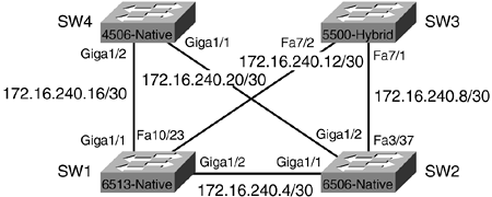
Figure 7-9 shows the completed switch connections, and all the network addresses assigned.
Figure 7-9. Completed Connections Between All Four Switches
Now that the basic connections between switches have been established, ports to be used for access layer devices, such as workstations and servers, will be configured.


