Understanding Multiple Spanning Tree
Multiple Spanning Tree (MST) implementation is defined by IEEE 802.1s. MST convergence is fast because it rides on top of RSTP. MST provides load-balancing capability without the scalability issues that are attached with legacy STP. MST allows for very large Layer 2 networks. It can accomplish this through various regions or domains that house specific Layer 2 devices. In the "Introducing Rapid Spanning Tree Protocol" section, the primary focus was on 802.1w. Here, the discussion is on the integration of 802.1s and 802.1w using Cisco switches.
Comparing MST to PVST+/CST
In PVST+, a single spanning-tree topology is built for each VLAN. Each VLAN will have its own legacy STP network. Consider the design shown in Figure 10-13. If there were 50 VLANs running among these three switches, there would have been 50 instances of spanning tree to maintain. PVST+ offers good load-balancing capability because of the granularity offered through 50 instances of spanning tree. For instance, Switch1 could be configured to be the Root for the even VLANs, while Switch2 would be the Root for the odd VLANs. At the same time, the two Root switches can be configured to be the secondary Root for each other's VLANs.
Figure 10-13. Switches in Triangle Design
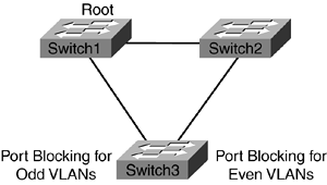
In Common Spanning Tree (CST) implementation, there would be one instance of spanning tree for all the VLANs. In Figure 10-13, Switch1 will be the Root for all the VLANs. As a result, there would be one instance of spanning tree. The negative side to CST is that the load-balancing capability is lost. Now, all user traffic is passed through Switch1. This is inefficient due to waste of critical bandwidth.
MST is a compromise between PVST+ and CST and offers numerous other advantages. Rather than creating 1 or 50 instances of spanning tree as defined by CST and PVST+, respectively, MST only creates two instances of spanning tree for the design shown in Figure 10-13. VLANs can be assigned arbitrarily to any instance. In this example, Switch1 handles even VLANs and Switch2 handles odd VLANs. MST provides load-balancing capability for groups of VLANs rather than each VLAN. It also uses the strength of CST by grouping VLANs to reduce the number of instances of VLANs in the network.
MST Regions
The mechanics involved on how MST manages to create only two instances of spanning tree in Figure 10-13 has to do with regions. A region, similar to an administration domain, is a collection of VLANs that have the same configuration and are managed under the same MST umbrella. In the example given, one region has two instances of spanning tree. Each region must have the same configuration for these three elements:
Region Name (32 bytes)
Revision Number (16 bits)
Associating VLANs with spanning-tree instances
Internal Spanning Tree
There must at least be two instances for MST, meaning at least two spanning-tree topologies. The first instance, Internal Spanning Tree (IST), is set at 0. The second instance is user defined. The IST instance extends the CST inside the MST region. The Layer 2 network essentially has two tiers: one CST and multiple MSTIs (MST instances). A total of 15 MSTIs plus 1 IST under one region can be configured.
Figure 10-14 illustrates the importance of IST. This figure shows two regions. Two switches are within Region 10. Switch2, which is part of Region 20, has a higher BID value than the other two switches. Hence, its superior BPDUs are accepted by Switch1 and Switch3 for IST instance. From Switch1 and Switch3's perspective, Switch2 is the Root for all the VLANs for MST 0 instance. Switch1 has an additional role to play. One of its ports is a boundary port, meaning that it is connected to a different region. When it receives the BPDU from Switch2, it first modifies the BPDU before forwarding it on to Switch3. It adds an IST Master ID and IST Master Path Cost to the BPDU. By default, the IST Master ID is the bridge ID and the Master Path Cost is 0.
Figure 10-14. CST Cloud
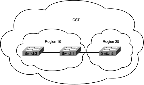
Two distinct methods exist for selecting an IST Master:
The Root for the CST that is inside the region will also be selected as IST Master. For example, Switch2 will also be the IST Master for Region 20.
The boundary bridge is defined as the smallest path cost to the CST Root. In Figure 10-14, that would be Switch1, because it has a direct connection to Switch2.
Figure 10-15 shows Switch1 adding the IST Master Path Cost, as depicted by the shaded boxes.
Figure 10-15. BPDU Entering MST Region

The objective of having an IST is to make the MST region appear as a single bridge. This is an important distinction because it allows for MST to have large Layer 2 networks. For instance, Region 10 is seen by other regions as one bridge with one port participating in spanning tree. The IST master bridge is used as transit by the local bridges within the region.
It is important to understand that one CST is available for the entire Layer 2 network. The CST topology is built based on IST. Also, remember that within the region, another spanning tree is locally significant to the region, as discussed in the next section.
Spanning Tree Inside the Region
In Figure 10-14, Region 10 and Region 20 have their own spanning-tree topology that is different from the CST spanning-tree topology. The locally significant spanning-tree topology is known as MSTI. There could be one instance or multiple instances depending on the design requirements. A region can have up to 15 MSTIs. Keep these three points in mind with respect to MSTI implementation:
MSTIs exist inside the region.
MSTIs have no direct interaction with outside the region.
MST sends 1 BPDU for all the instances in that region. Within the BPDU, an MSTP Record (M-record) is maintained for each of the instances. M-record contains spanning-tree information for an MSTI.
MST Example?All Switches in the Same Region
Take a look at an example to solidify some of these concepts. Remember, MST requires a minimum of 7.1(1) Catalyst OS code. Switch1 will be the Root for even VLANs, and Switch2 will be the Root for odd VLANs. All these switches (see Figure 10-16) will be located in the same MST region. Follow the configuration guidelines in Example 10-16.
Example 10-16. MST Configuration
Switch1 (enable) set spantree mst config name grp1 !Defining the name for the MST Switch1 (enable) set spantree mst config revision 10 !Revision number is set to 10 Switch1 (enable) set spantree mst config commit !Any changes to name and revision number requires a commit afterwards or else the changeswill not take effect Switch1 (enable) set spantree mode mst !Turning MST on. This command disables PVST+ Switch2 (enable) set spantree mst config name grp1 Switch2 (enable) set spantree mst config revision 10 Switch2 (enable) set spantree mst config commit Switch2 (enable) set spantree mode mst Switch3 (enable) set spantree mst config name grp1 Switch3 (enable) set spantree mst config revision 10 Switch3 (enable) set spantree mst config commit Switch3 (enable) set spantree mode mst
Figure 10-16. Switches in the Same Region
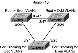
As mentioned in the "MST Regions" section, the configuration name, revision number, and VLAN mapping need to be the same for all the switches within the same region. The revision number is arbitrary and user defined. Ensure that ports connecting the switches are set to full duplex and are configured with IEEE 802.1Q trunking before commencing with MST configuration.
As noted on Switch1, the MST configuration name is grp1 with revision 10. Example 10-17 shows the only instance of IST that covers VLANS 1-4096. You need to now create two more instances for even and odd VLANs. Also, note in Example 10-17 that you can configure 15 additional MSTIs.
Example 10-17. MST Region Configuration
Switch1 (enable) show spantree mst config

Current (NVRAM) MST Region Configuration:

Configuration Name: grp1                               Revision: 10

Instance VLANs

-------- --------------------------------------------------------------

IST      1-4094

  1      -

  2      -

  3      -

  4      -

  5      -

  6      -

  7      -

  8      -

  9      -

 10      -

 11      -

 12      -

 13      -

 14      -

 15      -

=======================================================================
After creating the odd and even VLANs, as outlined in Example 10-18, commit them to the MST group.
Example 10-18. MST Load-Balancing Configuration
Switch1 (enable)set spantree mst 2 vlan 2,4,6,8,10,12,14,16,18,20,22,24,26,28,30,32,34,36,38,40,42,44,46,48,50 Switch1 (enable)set spantree mst 3 vlan 1,3,5,7,9,11,13,15,17,19,21,23,25,27,29,31,33,35
,37,39,41,43,45,47,49 Switch1 (enable)set spantree mst config commit Switch2 (enable)set spantree mst 2 vlan 2,4,6,8,10,12,14,16,18,20,22,24,26,28,30,32,34,36
,38,40,42,44,46,48,50 Switch2 (enable)set spantree mst 3 vlan 1,3,5,7,9,11,13,15,17,19,21,23,25,27,29,31,33,35
,37,39,41,43,45,47,49 Switch2 (enable)set spantree mst config commit Switch3 (enable)set spantree mst 2 vlan 2,4,6,8,10,12,14,16,18,20,22,24,26,28,30,32,34,36
,38,40,42,44,46,48,50 Switch3 (enable)set spantree mst 3 vlan 1,3,5,7,9,11,13,15,17,19,21,23,25,27,29,31,33,35
,37,39,41,43,45,47,49 Switch3 (enable)set spantree mst config commit
Once again, looking at the MSTI table, you can see that instances 2 and 3 are now defined. (See Example 10-19.)
Example 10-19. Update to MST Region Configuration
Switch1 (enable) show spantree mst config

Current (NVRAM) MST Region Configuration:

Configuration Name: grp1                               Revision: 10

Instance VLANs

-------- --------------------------------------------------------------

IST      51-4094

  1      -

  2      2,4,6,8,10,12,14,16,18,20,22,24,26,28,30,32,34,36,38,40,42,44

         46,48,50

  3      1,3,5,7,9,11,13,15,17,19,21,23,25,27,29,31,33,35,37,39,41,43

         45,47,49

  4      -

  5      -

  6      -

  7      -

  8      -

  9      -

 10      -

 11      -

 12      -

 13      -

 14      -

 15      -

=======================================================================
The last step required is to ensure that the appropriate switches are the Root for the VLANs. Switch1 and Switch2 have been configured to be Roots for even and odd VLANs in Example 10-20, respectively. The priority field has been reduced from 32771 to 24576 for both switches.
Example 10-20. MST Root for VLAN 2
Switch1 (enable) set spantree root mst 2

Instance 2 bridge priority set to 24576.

Instance 2 bridge max aging time set to 20.

Instance 2 bridge hello time set to 2.

Instance 2 bridge forward delay set to 15.

Switch2 (enable) set spantree root mst 3

Instance 3 bridge priority set to 24576.

Instance 3 bridge max aging time set to 20.

Instance 3 bridge hello time set to 2.

Instance 3 bridge forward delay set to 15.
Switch3 correctly recognizes Switch1 and Switch2 for their respective VLANs. The VLANs mapped information shows that Switch1 is the Root for all even VLANs (see Example 10-21), while Switch2 is the Root for all odd VLANs (see Example 10-22). The Role column shows the designation of the port with respect to the spanning-tree topology. Remember that the port role was defined by RSTP. The type field shows that all these ports are point to point, which means they are set at full duplex.
Example 10-21. MST Information for VLAN 2
Switch3 (enable) show spantree mst 2

Spanning tree mode          MST

Instance                    2

VLANs Mapped:               2,4,6,8,10,12,14,16,18,20,22,24,26,28,30,32,34,36

                            38,40,42,44,46,48,50

Designated Root             00-05-74-18-04-80

Designated Root Priority    24578  (root priority: 24576, sys ID ext: 2)

Designated Root Cost        200000     Remaining Hops 19

Designated Root Port        3/24

Bridge ID MAC ADDR          00-0b-fc-d4-23-80

Bridge ID Priority          32770  (bridge priority: 32768, sys ID ext: 2)

Port                     State         Role Cost     Prio Type

------------------------ ------------- ---- -------- ---- --------------------

 3/24                    forwarding    ROOT   200000   32 P2P

 3/25                    blocking      ALTR   200000   32 P2P

15/1                     forwarding    DESG    20000   32 P2P, Edge
Example 10-22. MST Information for VLAN 3
Switch3 (enable) show spantree mst 3

Spanning tree mode          MST

Instance                    3

VLANs Mapped:               1,3,5,7,9,11,13,15,17,19,21,23,25,27,29,31,33,35,37

                            39,41,43,45,47,49

Designated Root             00-01-63-29-bc-00

Designated Root Priority    24579  (root priority: 24576, sys ID ext: 3)

Designated Root Cost        200000     Remaining Hops 19

Designated Root Port        3/25

Bridge ID MAC ADDR          00-0b-fc-d4-23-80

Bridge ID Priority          32771  (bridge priority: 32768, sys ID ext: 3)

Port                     State         Role Cost     Prio Type

------------------------ ------------- ---- -------- ---- --------------------

 3/24                    blocking      ALTR   200000   32 P2P

 3/25                    forwarding    ROOT   200000   32 P2P

15/1                     forwarding    DESG    20000   32 P2P, Edge
You might have noticed the high costs associated with each port, as shown in Examples 10-21 and 10-22. These high values for ports are due to 802.1t implementation, which is mandatory with MST; 802.1t sets a 32-bit cost on port bandwidth. For instance, in legacy STP, the port cost for 10BASE-T port was at 100; now it is at 2,000,000. Table 10-2 shows the new values for each port based on its speed.
Bandwidth (Mbps) | New Value (802.1t) | Original Value |
|---|---|---|
10 | 2,000,000 | 100 |
100 | 200,000 | 19 |
1,000 | 20,000 | 4 |
10,000,000 | 2 |
In legacy STP, the BID field was composed of 2-byte priority plus 6-byte MAC address. Because 802.1t steals 12 bits from the priority field to compose the VLAN number, the priority field can now only take 16 values by increments of 4096. The new BID is as follows:
BID = Priority (4 bits) + VLAN number (12 bits) + MAC (6 bytes)
MST Example?Multiple Regions
This section illustrates the significance of IST and multiple MSTIs by describing a simple example where two different regions are implemented. In Figure 10-17, Switch1 and Switch3 are in Region 10. Switch2 is in Region 20. The default IST is the only other instance.
Figure 10-17. Multiple Regions
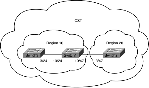
The first task is to define the two regions. Both Switch1 and Switch3 will have the same configuration. (See Example 10-23.)
Example 10-23. MST Configuration for Two Regions
Switch1 (enable) set spantree mst config name grp1

Switch1 (enable) set spantree mst config revision 10

Switch1 (enable) set spantree mst config commit

Switch1 (enable) set spantree mode mst

Switch3 (enable) set spantree mst config name grp1

Switch3 (enable) set spantree mst config revision 10

Switch3 (enable) set spantree mst config commit

Switch3 (enable) set spantree mode mst

Switch2 (enable) set spantree mst config name grp2

Switch2 (enable) set spantree mst config revision 20

Switch2 (enable) set spantree mst config commit

Switch2 (enable) set spantree mode mst
Switch1 and Switch2 in Example 10-24 are configured for grp1 and grp2, respectively.
Example 10-24. MST Region Configuration for Regions 10 and 20
Switch1 (enable) show spantree mst config

Current (NVRAM) MST Region Configuration:

Configuration Name: grp1                               Revision: 10

Instance VLANs

-------- --------------------------------------------------------------

IST      1-4094

Switch2 (enable) show spantree mst config

Current (NVRAM) MST Region Configuration:

Configuration Name: grp2                               Revision: 20

Instance VLANs

-------- --------------------------------------------------------------

IST      1-4094
IST instance makes a region appear as one bridge to the rest of the network. The MST 0 instance is the IST instance. From the output shown in Example 10-25, the bridge for the CST is Switch2, 00-01-63-29-bc-00. The designated RP to Switch2 correctly shows 10/47, which is directly connected to Switch2. Also, notice Master ID MAC address and IST Master Path Cost are different for the two regions. All other internal switches within the region will use the master bridge as a transit to other regions. The boundary key in the type field shows that ports 3/47 and 10/47 are connected to a different region.
Example 10-25. IST Spanning Tree Information for Switch1 and Switch2
Switch1 (enable) show spantree mst 0

Spanning tree mode          MST

Instance                    0

VLANs Mapped:               1-4094

Designated Root             00-01-63-29-bc-00

!Correctly sees Switch2 as the root for CST

Designated Root Priority    24576  (root priority: 24576, sys ID ext: 0)

Designated Root Cost        200000

Designated Root Port        10/47

Root Max Age   20 sec   Hello Time 2  sec   Forward Delay 15 sec

IST Master ID MAC ADDR      00-05-74-18-04-80

!the local bridge is the master bridge

IST Master ID Priority      32768

IST Master Path Cost        0          Remaining Hops 20

Bridge ID MAC ADDR          00-05-74-18-04-80

Bridge ID Priority          32768  (bridge priority: 32768, sys ID ext: 0)

Bridge Max Age 20 sec   Hello Time 2  sec   Forward Delay 15 sec  Max Hops 20

Port                     State         Role Cost     Prio Type

------------------------ ------------- ---- -------- ---- --------------------

10/24                    forwarding    DESG   200000   32 P2P

10/47                    forwarding    ROOT   200000   32 P2P, Boundary

15/1                     forwarding    DESG    20000   32 P2P, Edge


Switch2 (enable) show spantree mst 0

Spanning tree mode          MST

Instance                    0

VLANs Mapped:               1-4094

Designated Root             00-01-63-29-bc-00

!Root for the CST

Designated Root Priority    24576  (root priority: 24576, sys ID ext: 0)

Designated Root Cost        0

Designated Root Port        1/0

Root Max Age   20 sec   Hello Time 2  sec   Forward Delay 15 sec

IST Master ID MAC ADDR      00-01-63-29-bc-00

!The local bridge is the master bridge

IST Master ID Priority      24576

IST Master Path Cost        0          Remaining Hops 20

Bridge ID MAC ADDR          00-01-63-29-bc-00

!The local bridge is the root for CST

Bridge ID Priority          24576  (Bridge priority: 24576, sys ID ext: 0)

Bridge Max Age 20 sec   Hello Time 2  sec   Forward Delay 15 sec  Max Hops 20

Port                     State         Role Cost     Prio Type

------------------------ ------------- ---- -------- ---- --------------------

3/47                    forwarding    DESG   200000   32 P2P, Boundary

!Connected to a different region or legacy STP network

15/1                     forwarding    DESG    20000   32 P2P, Edge
Switch3 accepts Switch1 as the master bridge, as shown in Example 10-26.
Example 10-26. IST Spanning Tree Information for Switch3
Switch3 (enable) show spantree mst 0

Spanning tree mode          MST

Instance                    0

VLANs Mapped:               1-4094

Designated Root             00-01-63-29-bc-00

!Switch2 is seen as the Root for CST

Designated Root Priority    24576  (root priority: 24576, sys ID ext: 0)

Designated Root Cost        200000

Designated Root Port        3/24

Root Max Age   20 sec   Hello Time 2  sec   Forward Delay 15 sec

IST Master ID MAC ADDR      00-05-74-18-04-80

!Switch1 is seen as the master bridge for Region 10

IST Master ID Priority      32768

IST Master Path Cost        200000     Remaining Hops 19

Bridge ID MAC ADDR          00-0b-fc-d4-23-80

Bridge ID Priority          32768  (bridge priority: 32768, sys ID ext: 0)

Bridge Max Age 20 sec   Hello Time 2  sec   Forward Delay 15 sec  Max Hops 20

Port                     State         Role Cost     Prio Type

------------------------ ------------- ---- -------- ---- --------------------

 3/24                    forwarding    ROOT   200000   32 P2P

15/1                     forwarding    DESG    20000   32 P2P, Edge
So far, the discussion has been with the IST spanning tree. Let us create an MSTI within the regions. In Region 10, Switch1 will be the Root for the 50 VLANs. Also make Switch2 the Root for the same VLANs in Region 20. A red flag should rise. How can there be two Roots for the same VLANs? The simple answer is regions. Each region can have its own spanning-tree instances and they do not affect the spanning-tree instances of other regions. Follow the configuration shown in Example 10-27.
Example 10-27. Configuring Roots for VLANs 1-50
Switch1 (enable) set spantree mst 1 vlan 1-50

Switch1 (enable) set spantree mst config commit

Switch2 (enable) set spantree mst 1 vlan 1-50

Switch2 (enable) set spantree mst config commit

Switch3 (enable) set spantree mst 1 vlan 1-50

Switch3 (enable) set spantree mst config commit


Switch1 (enable) set spantree root mst 1

Instance 1 bridge max aging time set to 20.

Instance 1 bridge hello time set to 2.

Instance 1 bridge forward delay set to 15.


Switch2 (enable) set spantree root mst 1

Instance 1 bridge priority set to 24576.

Instance 1 bridge max aging time set to 20.

Instance 1 bridge hello time set to 2.

Instance 1 bridge forward delay set to 15.
Both Switch1 and Switch2 have been configured to be the Roots for VLANs 1-50 in their respective regions. Because these VLANs are only locally significant, no information exists regarding master bridge/path cost. An additional port designation appears under the Role Column. (See Example 10-28.) The BDRY role appears in the MSTI when the port is connected to a different region or legacy STP.
Example 10-28. Spanning-Tree Information for MST Instance 1
Switch1 (enable) show spantree mst 1

Spanning tree mode          MST

Instance                    1

VLANs Mapped:               1-50

Designated Root             00-05-74-18-04-80

!Notice Switch1 is the root for vlan 1-50

Designated Root Priority    24577  (root priority: 24576, sys ID ext: 1)

Designated Root Cost        0          Remaining Hops 20

Designated Root Port        1/0

Bridge ID MAC ADDR          00-05-74-18-04-80

Bridge ID Priority          24577  (bridge priority: 24576, sys ID ext: 1)

Port                     State         Role Cost     Prio Type

------------------------ ------------- ---- -------- ---- --------------------

10/24                    forwarding    DESG   200000   32 P2P

10/47                    forwarding    BDRY   200000   32 P2P, Boundary

15/1                     forwarding    DESG    20000   32 P2P, Edge

Switch2 (enable) show spantree mst 1

Spanning tree mode          MST

Instance                    1

VLANs Mapped:               1-50

Designated Root             00-01-63-29-bc-00

!Switch2 is the root in Region 20 for vlan 1-50

Designated Root Priority    24577  (root priority: 24576, sys ID ext: 1)

Designated Root Cost        0          Remaining Hops 20

Designated Root Port        1/0

Bridge ID MAC ADDR          00-01-63-29-bc-00

Bridge ID Priority          24577  (bridge priority: 24576, sys ID ext: 1)

Port                     State         Role Cost     Prio Type

------------------------ ------------- ---- -------- ---- --------------------

3/47                    forwarding    BDRY   200000   32 P2P, Boundary

15/1                     forwarding    DESG    20000   32 P2P, Edge
From Switch3's perspective, it sees only Switch1 as the Root for VLANs 1-50. (See Example 10-29.)
Example 10-29. Spanning-Tree Information for MST Instance 1
Switch3 (enable) show spantree mst 1

Spanning tree mode          MST

Instance                    1

VLANs Mapped:               1-50

Designated Root             00-05-74-18-04-80

!Switch1 is the Root

Designated Root Priority    24577  (root priority: 24576, sys ID ext: 1)

Designated Root Cost        200000     Remaining Hops 19

Designated Root Port        3/24

Bridge ID MAC ADDR          00-0b-fc-d4-23-80

Bridge ID Priority          32769  (bridge priority: 32768, sys ID ext: 1)

Port                     State         Role Cost     Prio Type

------------------------ ------------- ---- -------- ---- --------------------

 3/24                    forwarding    ROOT   200000   32 P2P

15/1                     forwarding    DESG    20000   32 P2P, Edge
MST Example?MST Connected to PVST+ Network
MST through IST will also be able to communicate with a non-MST bridge such as PVST+. From PVST+'s perspective, the MST region appears as one bridge. In Figure 10-18, Switch2 will now be PVST+ bridge. Switch1 recognizes its port 10/47 is connected to a non-MST bridge.
Figure 10-18. MST Connected to PVST+ Switch
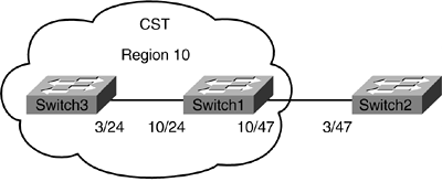
The BPDU it received contains information regarding who the Root is and the path cost to the Root. Switch1 will add the IST Master ID along with Master Path Cost and forwards the new BPDU to Switch3. This setup and behavior are no different if Switch2 was an MST-bridge. The only caveat is that because PVST+ does not understand 802.1w, the ports in the IST instance will lose their RSTP capability. Therefore, it is not recommended to have multiple modes of spanning tree in the network. Example 10-30 shows how to change back Switch2 to PVST+ mode.
Example 10-30. Changing the Switch to PVST+ Mode
Switch2 (enable) set spantree mode pvst+

Switch1 (enable) show spantree mst 0

Spanning tree mode          MST

Instance                    0

VLANs Mapped:               51-4094

Designated Root             00-01-63-29-bc-00

!The root is Switch2

Designated Root Priority    32768  (root priority: 32768, sys ID ext: 0)

Designated Root Cost        200000

Designated Root Port        10/47

Root Max Age   20 sec   Hello Time 2  sec   Forward Delay 15 sec

IST Master ID MAC ADDR      00-05-74-18-04-80

!Master bridge is local

IST Master ID Priority      32768

IST Master Path Cost        0          Remaining Hops 20

Bridge ID MAC ADDR          00-05-74-18-04-80

Bridge ID Priority          32768  (bridge priority: 32768, sys ID ext: 0)

Bridge Max Age 20 sec   Hello Time 2  sec   Forward Delay 15 sec  Max Hops 20

Port                     State         Role Cost     Prio Type

------------------------ ------------- ---- -------- ---- --------------------

10/24                    forwarding    DESG   200000   32 P2P

10/47                    forwarding    ROOT   200000   32 P2P, Boundary(PVST)

15/1                     forwarding    DESG    20000   32 P2P, Edge


