Spanning-Tree Convergence
Spanning-tree convergence issues have been a challenge for network administrators to address. Depending on the size of the Layer 2 network, it can get very complicated. In fact, one of the big selling points of RSTP is its superior convergence capability over the legacy STP. Cisco switches provide numerous commands that can be used to tweak specific spanning-tree timers as introduced in Chapter 1, and discussed in more depth in this section. Cisco has also made available features such as BackboneFast and UplinkFast to help converge the Layer 2 network faster.
Spanning-Tree Timers
Spanning-tree convergence issues can be tricky. It is recommended that you keep things as simple as possible at Layer 2. Keeping timers at default values is recommended because of the large majority of testing, network design certifications, and number of installations using default timers.
Spanning tree has various timers, including the following:
Hello? Root sends configuration BPDUs every 2 seconds.
set spantree hello interval [vlan]
Forward Delay? The time interval for listening and learning states. It is not, however, the sum of listening and learning state. The default for Forward Delay is set at 15 seconds.
set spantree fwddelay delay [vlan]
Maxage? The amount of time a switch saves configuration BPDUs. Maxage plays an important role during indirect failures. The default value for Maxage is 20 seconds.
set spantree maxage agingtime [vlan]
The diameter of the spanning network dictates how flexible the configuration of these parameters are. Typically, Hello and Forward Delay timers are not adjusted. There is some room, however, to adjust the Maxage timer.
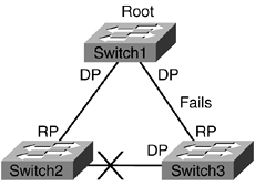
Figure 10-4 shows the amount of time it takes for an indirect link failure to occur before a blocking port transitions to forwarding.
Figure 10-4. Maxage Timer

The following steps outline how the Maxage timer works:
- Step 1. The connection between Switch1 and Switch3 fails.
- Step 2. Switch3 will start generating inferior configuration BPDUs toward Switch2.
- Step 3. Switch2 will ignore these BPDUs from Switch3 for 20 seconds, the Maxage timer.
- Step 4. After this timer expires, Switch2 will transition the blocking port to forwarding. This will take an additional 30 seconds.
- Step 5. Switch2 will forward configuration BPDUs from the Root (Switch1) to Switch2.
- Step 6. Switch2 will cease sending inferior BPDUs. The network has now converged.
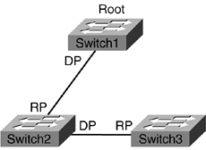
From the spanning-tree perspective, the network would look like Figure 10-5 after convergence. It took 50 seconds (20 seconds for Maxage + 30 seconds for listening/learning) for the network to converge. This type of outage is referred to as an indirect failure. If Switch2 lost its Root Port (RP), the convergence would have been 30 seconds. The blocking port would immediately go to listening state. This is known as a direct failure.
Figure 10-5. Spanning-Tree Convergence

The Maxage timer is composed of two elements. The first component is the diameter of the switches involved between the two hosts. It is generally accepted that there should be no more than seven switches between any two hosts. It is also acceptable that no more than three configuration BPDUs can potentially be lost:
Diameter=((lost BPDU + 1) * Hello Interval) + (Delay * (diameter - 1))
((3 + 1) * 2) + (1 * (7 - 1)) = 14 seconds
The second element involved in Maxage calculation is Message Age Overestimate. Each switch increments the Message Age field by 1 second as the configuration BPDU traverses through the switch. This 1-second value is overstated by the switch. Realistically, the switch can forward the BPDU much quicker than 1 second:
Message Age Overestimate=(diameter - 1) * delay
(7 - 1) * 1 = 6 seconds
Finally, the two values are taken together to come up with the 20-second Maxage default timer:
Maxage= Diameter + Message Age Overestimate
14 + 6 = 20 seconds
For example, if the diameter between two host machines is 3 bridges or switches, the Maxage could be set to 12 (10 + 2):
Diameter: ((3 + 1) * 2) + (1 * (3 - 1)) = 10 seconds
Message Age Overestimate: (3 - 1) * 1 = 2 seconds
BackboneFast
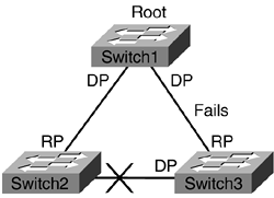
BackboneFast is a Maxage optimizer. (See Figure 10-6.) In other words, BackboneFast helps get rid of the 20 seconds that are associated with Maxage timer, which is used for indirect failures as mentioned in the previous section. BackboneFast does this by first detecting the indirect failure. The trigger for the indirect failure is when the switch receives inferior BPDUs on its blocking port. The second component to BackboneFast is verifying the failure. It does this through Root Link Query (RLQ) protocol. The switch sends RLQ requests to the upstream switch to find the location of the Root. Upon finding the location of the Root, the switch expires the Maxage timer and transitions the blocking port to listening state.
Figure 10-6. BackboneFast

BackboneFast process is outlined in the following steps:
- Step 1. The connection between Switch1 and Switch3 fails.
- Step 2. Switch3 will start generating inferior configuration BPDUs toward Switch2.
- Step 3. Upon receiving the inferior BPDUs, Switch2 sends a RLQ toward the upstream switch.
- Step 4. Switch1 sends back a RLQ response that it is the Root.
- Step 5. Switch2 now knows that it still has a path to the Root. It can now safely transition the blocked port.
- Step 6. Switch2 transitions the blocking port into listening state. It forwards configuration BPDUs to Switch3.
- Step 7. After 30 seconds, Switch3 has converged. This is the same amount of time for direct failure convergence.
BackboneFast is a global command, and it should be enabled on all switches, as shown in Example 10-10. BackboneFast does not affect direct failure convergence times.
Example 10-10. Enable BackboneFast
Switch2 (enable) set spantree backbonefast enable

Backbonefast enabled for all VLANs.
UplinkFast
UplinkFast is another feature that helps with the convergence issue. There must be redundant physical links on the access switch to the upstream switches to enable the UplinkFast feature. (See Figure 10-7.) One of the links is used for forwarding and the other link is used for backup. When the forwarding link fails, the backup link comes up and starts forwarding traffic. The convergence time is reduced to 2 to 3 seconds through this process. To help build the CAM table based on the new link, the switch sources all relevant MAC addresses that were associated with the link that failed and advertises them at a rate of 15 packets per 100 ms with a dummy multicast address, 01-00-0C-CD-CD-CD.
Figure 10-7. UplinkFast

If the UplinkFast feature is going to be used, it should only be configured on access switches. It is critical that UplinkFast not be enabled on core switches, because it could potentially cause some severe instability issues. In fact, when UplinkFast is enabled, by default, the switch sets the bridge priority to 49152 from its 32768. This is done to ensure that the access switch is not used as Root. Also, the cost on the switch ports is increased by 3000; so the switch is not used as transit by other switches.
In Figure 10-7, Switch2 is defined as the access switch. As noted in the spantree information (see Example 10-11), the switch has redundant links for VLAN 4 because one of its ports is in blocking mode. UplinkFast is a global command. The root priority and port cost are automatically adjusted when UplinkFast is enabled.
Example 10-11. Spanning Tree for VLAN 4
Switch2 (enable) show spantree 4

VLAN 4

Spanning tree mode          PVST+

Spanning tree type          ieee

Spanning tree enabled

Designated Root             00-05-74-18-04-80

Designated Root Priority    24580

Designated Root Cost        19

Designated Root Port        3/11

Root Max Age   20 sec   Hello Time 2  sec   Forward Delay 15 sec

Bridge ID MAC ADDR          00-01-63-29-bc-03

Bridge ID Priority          32768

Bridge Max Age 20 sec   Hello Time 2  sec   Forward Delay 15 sec

Port                     Vlan Port-State    Cost      Prio Portfast Channel_id

------------------------ ---- ------------- --------- ---- -------- ----------

 3/11                    4    forwarding           19   32 enabled  0

 3/12                    4    blocking             19   32 enabled  0
Example 10-12 shows the configuration involved in turning UplinkFast on a switch. The defaults for the bridge and ports have been adjusted accordingly.
Example 10-12. Uplinkfast Enabled
Switch2 (enable) set spantree uplinkfast enable

VLANs 1-4094 bridge priority set to 49152.

The port cost and portvlancost of all ports set to above 3000.

Station update rate set to 15 packets/100ms.
As noted, port 3/11 is forwarding while 3/12 is in backup state as shown in Example 10-13.
Example 10-13. Uplinkfast Currently Active on Port 3/11
Example 10-13

Switch2 (enable) show spantree uplinkfast

Station update rate set to 15 packets/100ms.

uplinkfast all-protocols field set to off.

VLAN          port list

-----------------------------------------------

4             3/11(fwd),3/12


