Campus Design
Although it is difficult to capture a "typical" campus network design in a single illustration, campus networks, in general, experience many common demands including support of large numbers of end users, servers, and the need for WAN connectivity to either the Internet or to other locations. Figure 11-7 illustrates a simple campus network design using the three-tiered core, distribution, access design principle, with the addition of a building block of dual-attached switches to accommodate servers.
Figure 11-7. Simple Campus Design
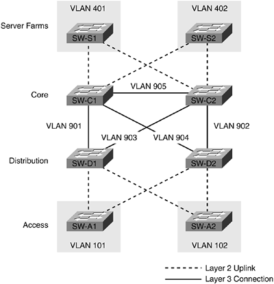
In this design, the building block outlined in the previous section is used at the access and distribution layer without the connection between SW-D1 and SW-D2. This design differs from the previous collapsed backbone design by incorporating a true core layer of switches with fully meshed connections to the distribution layer. Figure 11-7 uses the VLAN numbering scheme outlined in Chapter 7. The switches in the core and distribution layer are all capable of Layer 3 routing and are using networks with 30-bit subnet masks for VLANs 901?905. This creates a routed core infrastructure with only the access layer and server switches utilizing Layer 2 uplinks. Administrators that have experience with Cisco routers might recognize that the links between core switches are providing the functionality that was once provided by high-speed WAN links. In this configuration, the core and distribution switches are configured to run some type of dynamic routing protocol, such as OSPF or EIGRP, to facilitate routing and form neighbor relationships across their direct connections in VLANs 901?905. Refer to Chapter 7 for details on configuring dynamic routing protocols on Catalyst switches. It is assumed that in most designs the core and distribution switches will be higher-end platforms with more switching capacity, and links between core and distribution switches will be high speed. As a result, it is a good practice to avoid allowing the core and distribution switches to route traffic via access layer or server VLANs, such as 101 and 102 or 401 and 402. Routing via the access layer or server block can be disabled in most routing protocols by issuing a passive-interface command for each interface connecting to those VLANs. Example 11-1 changes gigabitethernet 1/1 on SW-D1 to passive mode for EIGRP.
TIP
Although the assignment of a VLAN number to Layer 3 interfaces is not necessary on switches using native software or the Cisco IOS interface, it is a best practice to follow a defined IP addressing and VLAN numbering scheme. Administrators may elect to pair VLAN numbers with IP network numbers even though actual configuration of those VLAN numbers on the switch is not necessary. This way, platforms that run hybrid software and require VLANs to be assigned can follow the same IP and VLAN numbering scheme.
Example 11-1. Passive Interface Command for EIGRP
SW-D1#config terminal

Enter configuration commands, one per line.  End with CNTL/Z.

SW-D1(config)#router eigrp 100

SW-D1(config-router)#passive-interface gigabitethernet 1/1

SW-D1(config-router)#end


SW-D1#show ip protocol

Routing Protocol is "eigrp 100"

  Outgoing update filter list for all interfaces is

  Incoming update filter list for all interfaces is

  Default networks flagged in outgoing updates

  Default networks accepted from incoming updates

  EIGRP metric weight K1=1, K2=0, K3=1, K4=0, K5=0

  EIGRP maximum hopcount 100

  EIGRP maximum metric variance 1

  Redistributing: eigrp 100

  Automatic network summarization is in effect

  Routing for Networks:

    172.16.192.0/18

  Passive Interface(s):

    GigabitEthernet1/1

  Routing Information Sources:

    Gateway     Distance   Last Update

    172.16.240.13     90   00:00:33

    172.16.240.6     90   2w2d

    172.16.240.18     90   1w0d

  Distance: internal 90 external 170
After the passive-interface command is issued successfully, the output from the show ip protocols command in Example 11-1 indicates the gigabitethernet 1/1 interface is passive for EIGRP. Refer to the documentation on Cisco.com for more information about disabling routing for protocols, such as OSPF and EIGRP, for specific interfaces.
Often, overlap exists between core, distribution, and access layer positioning when it comes to selecting a switching platform for each layer. As the switching capabilities of each of the Cisco platforms continue to grow, switches once used in a network core are sometimes redeployed in a distribution or even access layer as newer models or capabilities become available. This is no different than a Pentium II fileserver installed in 2000 being reused for a simpler function in 2004 in favor of a Pentium IV system. Cisco positions its higher-end platforms such as the Catalyst 6000/6500 as core and distribution switches, the Catalyst 4500 as a distribution and high-capacity closet switch, and the Catalyst 3750 as an access layer switching solution. Platform positioning is simply a guideline for placement of switches in a network and is not a hard and fast rule. Many networks run exclusively Catalyst 6500s in the core, distribution, and access layer, and others use what is typically considered a distribution switch in the core. The key is to match the switch capabilities with current and future network traffic.
In Figure 11-7, traffic routed between VLANs 101 and 102 is accomplished by the distribution switches SW-D1 and SW-D2, because no Layer 2 loops exist on those VLANs. Figure 11-8 again introduces Host 1 and Host 2 and illustrates the traffic flow between them should a link between the access layer and distribution layer fail.
Figure 11-8. Access Layer Link Failure
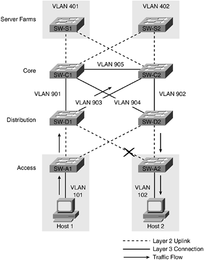
Because traffic from Host 1 is being sent to the active HSRP address on SW-D1 to be routed, when the link between SW-A2 and SW-D1 fails, SW-D1 recognizes a path in its routing table to VLAN 102 via SW-C2. This is due to SW-D2 advertising VLAN 102 via a dynamic routing protocol to each of its neighbors SW-C1 and SW-C2. The path from SW-A1 to VLAN 102 through SW-C2 is the shortest, assuming the bandwidth of each of the links connecting the core and distribution switches is identical, and no customization of routing metrics has been configured. In most networks, link failures between switches are not a frequent occurrence, and temporary routing of using an indirect path through the core is not an issue. If links between the switches in an environment fail often, bigger issues likely exist. One alternative to this design is to add another Layer 3 link between the distribution switches. This option and the resulting traffic flow are illustrated in Figure 11-9.
Figure 11-9. Addition of a Link Between SW-D1 and SW-D2
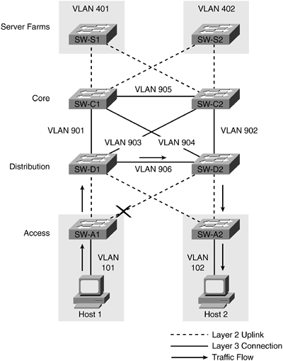
The link between SW-D1 and SW-D2 continues the VLAN numbering convention by using VLAN 906, and a dynamic routing neighbor relationship is formed between SW-D1 and SW-D2 using this link. As a result, when the link between the SW-A2 and SW-D1 is lost, traffic bypasses the core switches and is routed via the distribution layer. Seeing this new traffic flow, administrators may wonder why any design would exclude the link between SW-D1 and SW-D2. Although there is certainly nothing wrong with adding the link, it does add cost to the design because each pair of distribution switches will require an extra connection, and is really only useful in a scenario where an access layer link has failed or when a device is single attached to a distribution layer switch. Access layer failures should be rare, and single-attached devices to the distribution layer should be avoided whenever possible.
Traffic Flows
When designing any network, it is important to understand how the expected traffic from source to destination will be accommodated by the design. Figure 11-10 illustrates the expected traffic flow between Host 1 and Server 1.
Figure 11-10. Traffic Flow Between Host 1 and Server 1
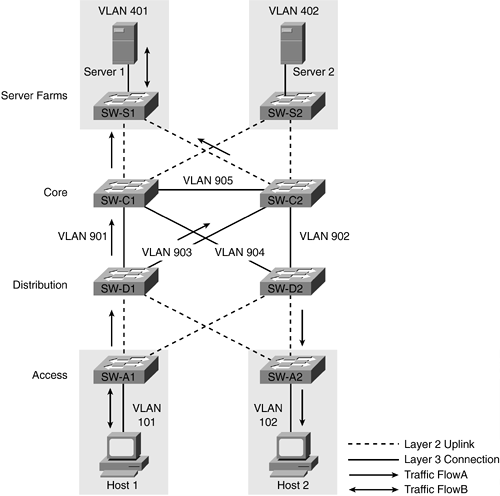
Host 1 is configured to use the active HSRP address for VLAN 101 on SW-D1 as its default gateway, and Server 1 is configured to use the active HSRP address for VLAN 401 on SW-C1 as its default gateway. Assuming all the links between the core and distribution switches are of equal speed, SW-D1 will have two paths in its routing table to VLAN 401. Dynamic routing protocols, such as EIGRP, automatically load balance traffic using up to four equal cost paths by default. You can adjust this behavior to use fewer than four paths or up to eight paths using the maximum-paths command. (See Example 11-2.) Normally, the default of four maximum paths is sufficient and should not be changed.
The same situation exists on the return path from Server 1 to Host 1 because SW-C1 has equal paths in its routing table to VLAN 101 via SW-D1 and SW-D2. In this situation, traffic returning from Server 1 to Host 1 might take a different path than traffic originating from Host 1 to Server 1. This behavior is described as asymmetrical routing and is typically not an issue for most types of traffic. Because return traffic can take multiple paths, some packets may be received out of order and must rely upon the application to reassemble the packets in the correct order. If a requirement exists to limit the traffic flow to one well-known path unless a link failure occurs, administrators might adjust the parameters of dynamic routing protocols to favor one path over another. In the case of EIGRP, you can adjust the delay parameter so that one route is preferred over another. Delay, and not bandwidth, should be increased on the links that should not be used during normal traffic flow. Once adjusted, if the preferred link fails, the link with the additional delay will be used. Example 11-3 shows the default delay of 10 microseconds on a GigabitEthernet interface and the possible values for delay. Delay is adjusted on an interface-by-interface basis.
Example 11-2. Maximum Paths Command for EIGRP
SW-D1#config t

Enter configuration commands, one per line. End with CNTL/Z.

SW-D1(config)#router eigrp 100

SW-D1(config-router)#maximum-paths ?

 <1-8> Number of paths
Example 11-3. Increasing EIGRP Delay
SW-D1#show interface gigabitethernet 1/1

GigabitEthernet1/1 is up, line protocol is up

  Hardware is C6k 1000Mb 802.3, address is 0005.7418.048a (bia 0005.7418.048a)

  Internet address is 172.16.240.17/30

  MTU 1500 bytes, BW 1000000 Kbit, DLY 10 usec,

     reliability 255/255, txload 1/255, rxload 1/255

  Encapsulation ARPA, loopback not set

  Keepalive set (10 sec)

  Full-duplex, 1000Mb/s

  ARP type: ARPA, ARP Timeout 04:00:00

  (output truncated)


SW-D1#config t

SW-D1#)config)interface GigabitEthernet1/1

SW-D1(config-if)#delay ?

  <1-16777215> Throughput delay (tens of microseconds)
Single Points of Failure
All networking organizations are forced to make choices about where they allow single points of failure to be designed into their networks. These choices are generally based on the cost to benefit ratio of eliminating each single point of failure. As a result, some single points of failure get eliminated, and some remain and are simply lived with. In Figure 11-11, one single point of failure from the previous figures has been eliminated by installing dual-network interface cards (NICs) into Server 1 and Server 2. Previously, a single cable failure from the server to the switch, a single NIC failure on the server, a single port or module failure on the switch, or an entire switch failure, would render the server unavailable. In Figure 11-11, each server is connected to both SW-S1 and SW-S2 to prevent those single points of failure from occurring.
Figure 11-11. Dual NICs in Servers 1 and 2
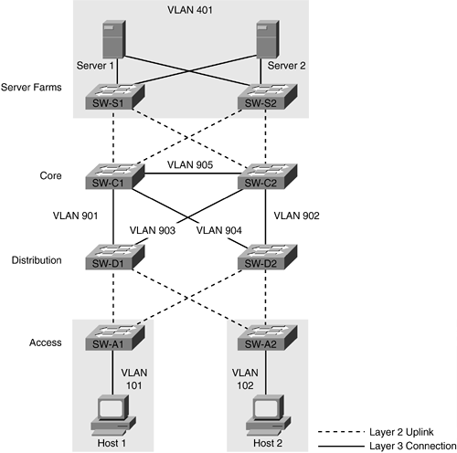
Although a wide range of NIC redundancy or "teaming" solutions exists from many vendors, virtually all require the two connections to be members of the same VLAN. In Figure 11-11, VLAN 402 is eliminated from the design and VLAN 401 is allowed to span both SW-S1 and SW-S2. This situation is an example of an unavoidable need to span VLANs across switches, and creates a Layer 2 loop in the topology that spanning tree must block. Other applications, such as wireless, currently rely on access points to be installed in the same VLAN for roaming to occur between access points. As a result, VLANs must span switches creating logical loops that must be managed by spanning tree.
With few exceptions, end-user hosts are always single attached to their access switches and are vulnerable to the same single component failures as servers. Because of the costs associated with creating redundant connections for each end user and the capability for most organizations to continue with minimal impact if a single user is down, this single point of failure is almost always not eliminated.
In reality, users don't care that Server 1 or Server 2 is available, they only care that applications running and data stored on Server 1 or Server 2 are available. Other options for eliminating a server single point of failure include content networking devices such as the Cisco CSS 11500 series, the server load-balancing features of Cisco IOS, and content services modules for the Catalyst 6500 series switches. Content networking allows you to load balance applications between multiple physical or "real" servers, while allowing users to point their workstations to one "virtual" server for their needs. Details on load-balancing operation and products can be found on the Cisco Systems website at Cisco.com.


