Introducing Virtual LANs
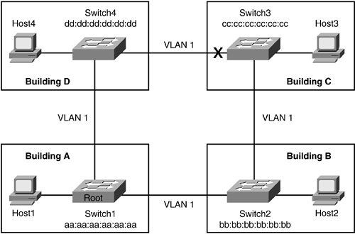
With the advent of VLANs, the same users in the legacy example are no longer restricted by physical cabling to be on the same logical segment or have the same access and privileges on the network. VLAN implementation makes the network more flexible as shown in Figure 4-2. Notice that one of the ports off Switch3 is crossed out in the drawing. Spanning tree has put that specific port into blocking state to prevent loops in the network as discussed in "Introducing Spanning Tree Protocol" section of Chapter 1.
Figure 4-2. Users Located in Multiple Buildings

In the legacy network, when a host moved to a different location on another router port, the IP address of the host had to be changed. Possible network changes were necessary to accommodate the user; for example, a change in a router access list allowing the user access back to a department server. The main point is that it was not easy to move users in the network without some type of change in the network or host. In an environment that supports VLANs, such network changes are not necessary because of flat Layer 2 network infrastructure. If Host1 in Figure 4-2 is moved to Building B, there is no need to change the configuration of the user's machine or the network. The user simply plugs the host into the jack and is ready to go.
NOTE
Keep in mind that the discussion thus far has been strictly focused on Layer 2, where a single VLAN is extended to multiple switches and with one instance of spanning tree.
Initially, there was big push to extend VLANs across the network. In fact, most universities implemented this technology because the implementation was relatively simple, and many applications at the time had a requirement to be on the same Layer 2 network because of their communications protocols. Network engineers simply configured a VLAN with a large IP range. They pushed security and other network policies on these VLANs on the fly. This was great in saving time and money.
The risks associated with such an implementation were quickly noticed. Extending VLANs has a dark side, enlarging the broadcast domain. If a single host sends out a broadcast message, every machine on that VLAN, regardless of the number of buildings and switches involved, receives that broadcast message. The result is excessive traffic on the network. The greater penalty is a broadcast storm, occurring when a host sends an incorrect broadcast message that is received by all hosts on that VLAN, and all those hosts broadcast as well. This process can eventually bring a flat Layer 2 network to its knees.
Spanning trees can also bring the network down when VLANs are extended across the switched network. Too much traffic on the network or some partial or complete hardware failure can cause a spanning-tree outage. In a spanning-tree outage, spanning tree is unable to calculate a loop-free topology correctly, and a loop occurs in the network. Similar to the example of a loop in transparent bridging, traffic exponentially increases causing a network meltdown until the loop is broken, many times requiring manual intervention.
A VLAN is tagged with a user-defined number to differentiate it from another VLAN. For instance, users on VLAN 4 are members of the same subnet and are on the same broadcast domain, whereas VLAN 5 has its own users and broadcast domain. Typically an enterprise switch has no more than 30 VLANs configured on a switch. Depending on the trunking mechanism used, the number of VLANs configured on a switch can be as high as 4096 minus some reserved VLANS. The "Trunking Methods" section later in this chapter discusses trunking further.
Table 4-1 provides the valid range of VLANs that can be configured on a switch. The Catalyst 5500 switch does not support the extended VLANs that fall in the 1025?4096 range. The trunking mechanism used might limit the number of VLANs available for use. For example, Inter-Switch Link (ISL) does not support extended VLAN range. The "VLAN Trunking Protocol" section later in this chapter will discuss VTP further.
VLANs | Range | Usage | Propagated by VTP (Y/N) |
|---|---|---|---|
0 and 4095 | Reserved range | For system use only. You cannot see or use these VLANs. | N/A |
1 | Normal range | Cisco default. You can use this VLAN but you cannot delete it. | Yes |
2?1000 | Normal range | Used for Ethernet VLANs. You can create, use, and delete these VLANs. | Yes |
1001 | Normal range | You cannot create or use this VLAN. May be available in the future. | Yes |
1002?1005 | Reserved range | Cisco defaults for FDDI and Token Ring. Not supported on Catalyst 6000 family switches. You cannot delete these VLANs. | N/A |
1006?1009 | Reserved range | Cisco defaults. Not currently used but might be used for defaults in the future. Nonreserved VLANs may be mapped to these reserved VLANs when necessary. | N/A |
1010-1024 | Reserved range | These VLANs might not be seen, but can be mapped to nonreserved VLANs when necessary. | N/A |
1025-4094 | Extended range | For Ethernet VLANs only. These may be created, used, and deleted with the following exception: FlexWAN modules and routed ports automatically allocate a sequential block of internal VLANs starting at VLAN 1025. If the devices are used, the required number of VLANs must be allowed for. | No |


