IGMP Snooping
IGMP snooping prevents multicast flows from flooding to all ports on a VLAN by monitoring the Layer 3 IGMP packets. Multicast streams are sent to ports that explicitly request the flow. The switch via the IGMP snooping mechanism listens to the conversation between the router and the host machine. The switch learns at Layer 3 which port is signaling for or leaving a multicast group. The switching engine forwards this message to the Network Management Processor (NMP), where the port is added to or removed from the Layer 2 multicast forwarding group based on the IGMP message type.
The first step that is required for IGMP snooping is that the switch needs to learn the router port. Typically, a Protocol Independent Multicast (PIM) hello message signals the switch where the router port is located. The following messages are used for locating the router port:
IGMP Group Membership Queries (01-00-5e-00-00-01 or 224.0.0.1)
PIM v1 Queries (01-00-5e-00-00-02 or 224.0.0.2)
PIM v2 Queries (01-00-5e-00-00-0d or 224.0.0.13)
DVMRP messages (01-00-5e-00-00-04 or 224.0.0.4)
MOSPF messages (01-00-5e-00-00-05 or 224.0.0.5 and 01-00-5e-00-00-06 or 224.0.0.6)
Figure 9-4 shows that the source and receivers are directly connected to the same switch. The switch has a multilayer switch feature card (MSFC), which will handle inter-VLAN communication. Therefore, the MSFC, port 15/1, will be the router port.
Figure 9-4. IGMP Snooping
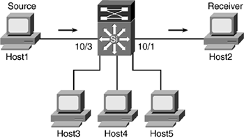
Membership Report
This section reviews various IGMP snooping scenarios.
Scenario 1: IGMP Snooping Process Between Source and Receiver on the Same VLAN
This scenario will go step by step through the IGMP snooping process (refer to Figure 9-4). The first objective is to know what the configuration looks like on the router, as shown in Example 9-3. The router is configured with PIMv2 and the PIM query interval is set at 30 seconds. The DR is the local router, MSFC, 10.1.3.10. At this point, only VLAN 3 is configured for multicast.
Example 9-3. IGMP Configuration on the Router and Switch
msfc_15#show ip pim interface vlan3

Address          Interface                Version/Mode    Nbr   Query     DR

                                                          Count Intvl

10.1.3.10        Vlan3                    v2/Sparse-Dense  1    30     10.1.3.10
In Catalyst 6500 switches, IGMP snooping is enabled by default. (See Example 9-4.) Note that RGMP and GMRP are beyond the scope of this book and will not be discussed.
Example 9-4. Supervisor Multicast Information
Switch1 (enable) show multicast protocols status

IGMP enabled

IGMP fastleave disabled

RGMP disabled

GMRP disabled
Example 9-5 shows the IGMP max query response set at 10 seconds. A router must receive a membership report within the max query response time interval, or else it will prune the interface. The Last member query response interval allows for the router to check once more before pruning the interface. The Multicast groups joined shows the multicast groups that the router knows on VLAN 3.
Example 9-5. IGMP Interface Information
msfc_15#show ip igmp interface vlan 3

Vlan3 is up, line protocol is up

  Internet address is 10.1.3.10/24

  IGMP is enabled on interface

  Current IGMP host version is 2

  Current IGMP router version is 2

  IGMP query interval is 60 seconds

  IGMP querier timeout is 120 seconds

  IGMP max query response time is 10 seconds

  Last member query response interval is 1000 ms

  Inbound IGMP access group is not set

  IGMP activity: 2 joins, 0 leaves

  Multicast routing is enabled on interface

  Multicast TTL threshold is 0

  Multicast designated router (DR) is 10.1.3.10 (this system)

  IGMP querying router is 10.1.3.10

  Multicast groups joined (number of users):

      239.1.1.1(1) 224.0.1.40(1)
The show igmp groupinfo, a hidden command, will show whether or not the multicast traffic from the source has any receivers. In Example 9-6, the multicast source only field isset at false, which means that receivers exist for the 239.1.1.1 traffic. If the value was set at true, the source is sending traffic but no receivers exist to get the multicast stream. The show IGMP groupinfo command can be useful when troubleshooting multicast-related issues.
Example 9-6. Multicast Source Only
Switch1 (enable) show igmp groupinfo 3 01-00-5e-01-01-01

MAC Address:              01-00-5e-01-01-01

Multicast Flag:           TRUE

confMask:                [0-4-0-0]

ltl_index:                0x500

mcast_info->protocol_type 2 = PROTO_TYPE_IGMP

mcast_info->protocol_type->info::

tx_v1_report:                FALSE

tx_v2_report:                TRUE

wait_count:               0

mcast_source_only:        FALSE

IP Address:               239.1.1.1

Host List::               15/1

Router Port  List::       10/1,15/1

User Conf Port List::     <null>

V1 Host List::

report_rx_portlist::      15/1
The following steps outline the IGMP snooping process for the first host on VLAN 3 that sends a membership report for group 239.1.1.1:
- Step 1. Host2 sends an unsolicited IGMP membership report to 239.1.1.1. The MSFC, port 15/1, is the router port for this traffic:
Switch1 (enable) show multicast router

Port       Vlan

---------- ----------------

15/1       3

Total Number of Entries = 3

'*' - Configured

'+' - RGMP-capable
- Step 2. The switch that intercepted the IGMP message creates an EARL entry for Host2:
MCAST-IGMPQ:recvd an IGMP V2 Report on the port 10/1 vlanNo 3 GDA

  239.1.1.1

     In ModifyMulticastEarlEntry

     Creating new entry because it's the first Node

     Creating initial node in ModifyMulticast

     Updating portlist for initial hostlist add
The entry now is in the multicast forwarding table for the Group Destination Address (GDA), 239.1.1.1 (01-00-5e-01-01-01):
Switch1 (enable) show multicast group 01-00-5e-01-01-01

VLAN  Dest MAC/Route Des   [CoS]  Destination Ports or VCs/[Protocol Type]

----  ------------------   -----  ---------------------------------------

3     01-00-5e-01-01-01           10/1,15/1
Multicast MAC addresses that appear in the forwarding table are stored as static entries in the CAM table. From the switch perspective, 239.1.1.1 is now associated with ports 10/1 and 15/1 on VLAN 3:
Switch1 (enable) show cam static 3

* = Static Entry. + = Permanent Entry. # = System Entry. R = Router Entry.

X = Port Security Entry $ = Dot1x Security Entry

VLAN  Dest MAC/Route Des  [CoS]  Destination Ports or VCs/[Protocol Type]

----  ------------------  -----  ---------------------------------------

3     01-00-5e-00-01-28           10/1,15/1

3     01-00-5e-01-01-01           10/1,15/1
- Step 3. The switch then sends the IGMP packet to the MSFC on port 15/1:
MCAST-RELAY:Relaying packet on port 15/1 vlanNo 3 MCAST-SEND: Inband Transmit Succeeded for IGMP RELAY msg on port 15/1 vlanNo 3 - Step 4. The router receives the unsolicited IGMP Join from the receiver, Host2 with an IP address of 10.1.3.2:
*Sep 30 05:58:47.830: IGMP: Received v2 Report on Vlan3 from 10.1.3.2 for 239.1. 1.1 - Step 5. The MSFC updates its IGMP membership table. The IGMP group membership provides information on the last host that requested the multicast traffic for that subnet:
msfc_15#show ip igmp group

IGMP Connected Group Membership

Group Address    Interface           Uptime    Expires   Last Reporter

239.1.1.1        Vlan3               00:21:54  00:02:39  10.1.3.2
- Step 6. Next, the MSFC populates the mroute table, which is the equivalent of the IP route table for multicast. It will create the (*, g) and (S, G) entries for 239.1.1.1 and forward the traffic out on VLAN 3:
msfc_15#show ip mroute 239.1.1.1

IP Multicast Routing Table

Flags: D - Dense, S - Sparse, s - SSM Group, C - Connected, L - Local,

       P - Pruned, R - RP-bit set, F - Register flag, T - SPT-bit set,

      J - Join SPT, M - MSDP created entry, X - Proxy Join Timer Running

      A - Advertised via MSDP, U - URD, I - Received Source Specific Host

           Report

Outgoing interface flags: H - Hardware switched

Timers: Uptime/Expires

Interface state: Interface, Next-Hop or VCD, State/Mode

(*, 239.1.1.1), 00:06:25/00:02:59, RP 0.0.0.0, flags: DJC

  Incoming interface: Null, RPF nbr 0.0.0.0

  Outgoing interface list:

    Vlan3, Forward/Sparse-Dense, 00:06:25/00:00:00

(10.1.3.5, 239.1.1.1), 00:00:18/00:02:41, flags: PCT

  Incoming interface: Vlan3, RPF nbr 0.0.0.0

  Outgoing interface list: Null
- Step 7. Multicast multilayer switching (MMLS) is enabled by default on Catalyst 6500 switches. In this case, because both source and destination are on the same VLAN, no hardware shortcut is created on the MSFC. This flow is already being handled by hardware switching. As a result, there will be no multicast MLS entry:
msfc_15#show mls ip multicast group 239.1.1.1

Multicast hardware switched flows:

Total hardware switched flows : 0

Switch1 (enable) show mls multicast entry

Router-IP       Dest-IP         Source-IP       Pkts                 Bytes

          InVlan Type OutVlans

--------------- --------------- --------------- -------------------- -

--------- ------ ---- -------------------------------------------

Total Entries Displayed: 0 (0 complete flow (C) and 0 partial flow (P))
Scenario 2: IGMP Snooping Process Between the Source and a Second Receiver on the Same VLAN
Figure 9-5 illustrates what happens when a second host from the same VLAN sends a membership report to the router.
Figure 9-5. Host3 Sends a Membership Report
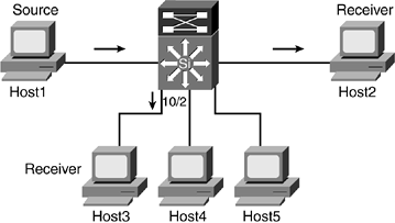
The following explains the process:
- Step 1. Host3, on port 10/2, sends an unsolicited IGMP membership report to 239.1.1.1.
- Step 2. The switch intercepts the IGMP message:
MCAST-IGMPQ:recvd an IGMP V2 Report on the port 10/2 vlanNo 3 GDA

  239.1.1.1

     In ModifyMulticastEarlEntry
The multicast forwarding table is updated with port 10/2:
Switch1 (enable) show multicast group 01-00-5e-01-01-01

VLAN  Dest MAC/Route Des   [CoS]  Destination Ports or VCs/[Protocol Type]

----  ------------------   -----  ---------------------------------------

3     01-00-5e-01-01-01              10/1-2,15/1
- Step 3. The switch then sends the IGMP packet to the MSFC on port 15/1:
MCAST-RELAY:Relaying packet on port 15/1 vlanNo 3 MCAST-SEND: Inband Transmit Succeeded for IGMP RELAY msg on port 15/1 vlanNo 3 - Step 4. The router receives the unsolicited IGMP Join from the receiver:
*Sep 30 06:07:41.434: IGMP: Received v2 Report on Vlan3 from 10.1.3.3

  for 239.1.

1.1
- Step 5. MSFC updates its IGMP membership table:
msfc_15#show ip igmp group IGMP Connected Group Membership Group Address Interface Uptime Expires Last Reporter 239.1.1.1 Vlan3 00:31:16 00:02:11 10.1.3.3 - Step 6. Because the MSFC already has an outgoing interface (OIF) for VLAN 3, it will not do anything on the mroute table.
- Step 7. No changes are made to the MMLS table. The MSFC does not send any shortcut information to the MMLS-Switching Engine (MMLS-SE) because Host3 is also part of VLAN 3:
msfc_15#show mls ip multicast group 239.1.1.1

Multicast hardware switched flows:

Total hardware switched flows : 0

Switch#1 (enable) show mls multicast entry

Router-IP       Dest-IP         Source-IP       Pkts                 Bytes

          InVlan Type OutVlans

--------------- --------------- --------------- -------------------- -----------

--------- ------ ---- -------------------------------------------

Total Entries Displayed: 0 (0 complete flow (C) and 0 partial flow (P))
Scenario 3: IGMP Snooping Process Between Source and Receiver on Different VLANs
Host4 from a different VLAN has requested the multicast stream 239.1.1.1. (See Figure 9-6.)
Figure 9-6. Host4 Sends a Membership Report
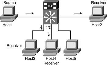
A hardware shortcut is created by the MSFC in this scenario because traffic is between different VLANs:
- Step 1. Host4, on port 1/2, sends an unsolicited IGMP membership report to 239.1.1.1.
- Step 2. The switch intercepts the IGMP message:
MCAST-IGMPQ:recvd an IGMP V2 Report on the port 1/2 vlanNo 30 GDA

  239.1.1.1

     In ModifyMulticastEarlEntry

     Creating new entry because it's the first Node

     Creating initial node in ModifyMulticast

     Updating portlist for initial hostlist add
The multicast forwarding table adds an additional line for VLAN 30 and its associate port of 1/2 for Host4:
Switch1 (enable) show multicast group

VLAN  Dest MAC/Route Des    [CoS]  Destination Ports or VCs/[Protocol Type]

----  ------------------    -----   --------------------------------------

3     01-00-5e-01-01-01             10/1-2,15/1

30    01-00-5e-01-01-01             1/2,15/1
- Step 3. The switch then sends the IGMP packet to the MSFC on port 15/1:
MCAST-RELAY:Relaying packet on port 15/1 vlanNo 30 MCAST-SEND: Inband Transmit Succeeded for IGMP RELAY msg on port 15/1 vlanNo 30 - Step 4. The router receives the unsolicited IGMP Join from the receiver:
*Sep 30 09:06:58.881: IGMP: Received v2 Report on Vlan30 from 10.1.4.1 for 239.1.1.15. The

 MSFC updates its IGMP membership table.
- Step 5. The router updates its IGMP membership table:
msfc_15#show ip igmp groups

IGMP Connected Group Membership

Group Address    Interface           Uptime    Expires   Last Reporter

239.1.1.1        Vlan30              00:00:46  00:02:55  10.1.4.1
- Step 6. Interface VLAN 30 is added to the OIF list. The letter H denotes hardware switched:
msfc_15#show ip mroute 239.1.1.1

IP Multicast Routing Table

Flags: D - Dense, S - Sparse, s - SSM Group, C - Connected, L - Local,

       P - Pruned, R - RP-bit set, F - Register flag, T - SPT-bit set,

      J - Join SPT, M - MSDP created entry, X - Proxy Join Timer Running

      A - Advertised via MSDP, U - URD, I - Received Source Specific Host

           Report

Outgoing interface flags: H - Hardware switched

Timers: Uptime/Expires

Interface state: Interface, Next-Hop or VCD, State/Mode

(*, 239.1.1.1), 00:05:45/00:02:59, RP 0.0.0.0, flags: DJC

  Incoming interface: Null, RPF nbr 0.0.0.0

  Outgoing interface list:

    Vlan3, Forward/Sparse-Dense, 00:01:44/00:00:00

    Vlan30, Forward/Sparse-Dense, 00:05:45/00:00:00

(10.1.3.5, 239.1.1.1), 00:00:21/00:02:59, flags: CT

  Incoming interface: Vlan3, RPF nbr 0.0.0.0, RPF-MFD

  Outgoing interface list:

    Vlan30, Forward/Sparse-Dense, 00:00:21/00:00:00, H
- Step 7. The packets are now hardware switched between VLAN 3, the multicast source, and VLAN 30, Host4, for 239.1.1.1 traffic:
msfc_15#show mls ip multicast group 239.1.1.1

Multicast hardware switched flows:

(10.1.3.5, 239.1.1.1) Incoming interface: Vlan3, Packets switched:

  508380

Hardware switched outgoing interfaces: Vlan30

RPF-MFD installed

Total hardware switched flows : 1
An MMLS entry is created because the multicast packets are hardware switched:
Switch1 (enable) show mls multicast entry

Router-IP       Dest-IP         Source-IP       Pkts                 Bytes

          InVlan Type OutVlans

--------------- --------------- --------------- -------------------- -----------

--------- ------ ---- -------------------------------------------

10.1.3.10       239.1.1.1       10.1.3.5        534751               794639986

          3      C    30

Total Entries Displayed: 1 (1 complete flow (C) and 0 partial flow (P))
For the MMLS entry to be created and updated, the MMLS-route processor (MMLS-RP), MSFC, and the MMLS-SE, the supervisor, must communicate with each other to ensure consistent data on both devices. The show multicast statistics command displays communication information between the MMLS-RP and MMLS-SE. (See Example 9-7.)
Example 9-7. Multicast Statistics on the Switch
Switch1 (enable) show mls multicast statistics

Router IP          Router Name        Router MAC

---------------    ------------------ -----------------

10.1.3.10          ?                  00-05-5e-96-76-c0

Transmit:

                     Feature Notifications: 0

            Feature Notification Responses: 2

           Shortcut Notification Responses: 3

!Switch's response back to the MSFC regarding the shortcut messages


                      Delete Notifications: 0

                           Flow Statistics: 47

                   Total Transmit Failures: 0

Receive:

                     Feature Notifications: 2

                         Shortcut Messages: 3


! Switch received 3 shortcut messages from the MSFC


               Duplicate Shortcut Messages: 0

                      Shortcut Install TLV: 1

!One hardware shortcut created


                      Selective Delete TLV: 0

                          Group Delete TLV: 0

                                Update TLV: 0

                     Input VLAN Delete TLV: 0

                    Output VLAN Delete TLV: 0

                         Global Delete TLV: 0

                           MFD Install TLV: 1

                            MFD Delete TLV: 0

                     Global MFD Delete TLV: 0

                               Invalid TLV: 0
The next section discusses what happens when a receiver leaves a multicast group, and how IGMP snooping handles such an event.
IGMP Leave Process
This section explores two types of leave process. The first leave process involves a single host leaving a multicast session while other hosts from the same VLAN are still receiving the multicast traffic. In the second example, the host is the last member to leave a multicast session.
The IGMP query router, MSFC, will send queries every 60 seconds to both VLAN 3 and VLAN 30 to check for members for the multicast group 239.1.1.1 (refer to Figure 9-6). As these queries are sent by the router to the switch, the switch forwards the queries to ports that are participating in the multicast session. Upon receiving the query message, the hosts will send back an IGMP membership report. The switch again intercepts these IGMP messages from the hosts and only forwards one membership report to the MSFC. A router does not need to receive membership reports from more than one host from a single VLAN for a multicast traffic. So long as there is one host, the multicast stream still needs to be forwarded to that interface. For this reason, the switch drops the other IGMP membership reports.
Scenario 1: IGMP Snooping Leave Process Between the Source and Multiple Receivers on the Same VLAN
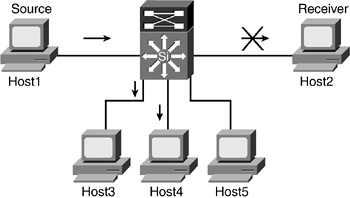
Figure 9-7 and the subsequent steps outlined address the issue of a receiver leaving a multicast group while another receiver on the same VLAN is still interested in the traffic.
- Step 1. Host2 sends a leave group message to all routers, 224.0.0.2, for multicast traffic 239.1.1.1.
- Step 2. The Catalyst switch intercepts the IGMP leave message:
MCAST-IGMPQ:recvd an IGMP Leave on the port 10/1 vlanNo 3 GDA 239.1.1.1
- Step 3. The switch sends a MAC-based general query to port 10/1. A random deletion timer value (1 to 3 seconds) will be set. If the host is communicating via IGMPv1, the random deletion timer is set at 10 seconds:
MCAST-DEL-TIMER: Deletion Timer Value set to Random Value 3
- Step 4. If the switch does not hear a membership report during the random deletion timer, it will drop the port from its multicast forwarding table:
MCAST-TIMER:IGMPLeaveTimer expired on port 10/1 vlanNo 3 GDA 01-00-5e-

  01-01-01

Delete UpdatePortOnMulticast
- Step 5. The switch does not send the IGMP leave message to the MSFC because the switch knows that Host3, which is on the same VLAN as Host2, is still accepting the 239.1.1.1 traffic. The MSFC does not even know that Host2 has left the multicast group. Also, no changes have been made to the MMLS table because Host3 on the VLAN 3 is still accepting the traffic.
Figure 9-7. Host2 Sends an IGMP Leave
Scenario 2: IGMP Snooping Leave Process Between the Source and Last Receivers
Figure 9-8 illustrates the last receiver, Host4, on VLAN 30 leaving the multicast group 239.1.1.1. When Host4 leaves the multicast group, both switch and MSFC will have to update their appropriate tables.
Figure 9-8. Host4 Sends IGMP Leave
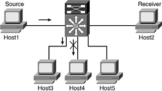
The following steps outline the IGMP snooping process when Host4 leaves the multicast group.
- Step 1. Host4 sends a leave group message to all routers, 224.0.0.2, for multicast traffic 239.1.1.1.
- Step 2. The Catalyst switch intercepts the IGMP leave message:
MCAST-IGMPQ:recvd an IGMP Leave on the port 1/2 vlanNo 30 GDA 239.1.1.1
- Step 3. The switch sends a MAC-based general query to port 1/2:
MCAST-DEL-TIMER: Deletion Timer Value set to Random Value 3
- Step 4. The switch updates its multicast forwarding table:
In ModifyMulticastEarlEntry Delete UpdatePortOnMulticast Delete UpdatePortOnMulticast - Last Port - Step 5. Because Host4 is the last member for the multicast group, the switch forwards an IGMP leave message to the MSFC:
MCAST-SEND:Transmitting IGMP Leave msg on port 15/1 vlanNo 30
- Step 6. Upon receiving the IGMP leave message, the MSFC sends two group-specific queries to check for any members for VLAN 30:
IGMP: Received Leave from 10.1.4.1 (Vlan30) for 239.1.1.1

IGMP: Send v2 Query on Vlan4 to 239.1.1.1

IGMP: Send v2 Query on Vlan4 to 239.1.1.1
- Step 7. Not hearing any response, MSFC deletes multicast traffic 239.1.1.1 to VLAN 30:
IGMP: Deleting 239.1.1.1 on Vlan30
- Step 8. The MSFC updates the MMLS-SE engine to clear the shortcut between VLAN 3 and VLAN 30 for the multicast 239.1.1.1 traffic.
IGMP Fastleave
With IGMP fastleave enabled, the switch removes the port from the multicast forwarding table without sending a MAC-based query to the port. The purpose behind fastleave is to quickly transition the port or VLAN off the multicast stream. Most customers have not deployed fastleave today. Fastleave should not be enabled on ports that have hubs connected to them. For example, two hosts are off the same hub, which is connected to a port on a Catalyst switch with IGMP fastleave enabled. If one host leaves, the switch immediately takes the port off the multicast forwarding table. As a result, the second host on the hub will lose its multicast traffic. IGMP fastleave is disabled on trunk ports.
Address Aliasing
Address aliasing is defined as mapping 32 multicast IP addresses to a single Layer 2 MAC address. A multicast Layer 3 address could map to a system MAC address that is used by the switch, which is a potential risk. Any packets destined to the system CAM entries are directly sent to the NMP because it is assumed that the packets are part of the control traffic rather than user traffic. As a result, network outages can occur if multicast user traffic is mapped to a system CAM entry.
Look at an example to solidify the problem with address aliasing. Both Host1 and Host2 are in VLAN 3 as shown in Figure 9-9. Two types of supervisors are used in this design. Their handling of address aliasing will become apparent shortly.
Figure 9-9. Address Aliasing

Example 9-8 shows two outputs from Switch1 and Switch2, respectively.
Example 9-8. System CAM Entries for VLAN 3
Switch1 (enable) show cam system 3

* = Static Entry. + = Permanent Entry. # = System Entry. R = Router Entry.

X = Port Security Entry $ = Dot1x Security Entry

VLAN  Dest MAC/Route Des    [CoS]  Destination Ports or VCs / [Protocol Type]

----  ------------------    -----  -------------------------------------------

3     00-00-0c-07-ac-03 R#          15/1

3     00-05-74-18-04-bc R#          15/1

3     01-00-0c-cc-cc-cc  #          1/3

3     01-00-0c-cc-cc-cd  #          1/3

3     01-00-0c-dd-dd-dd  #          1/3

3     01-80-c2-00-00-00  #          1/3

3     01-80-c2-00-00-01  #          1/3

Total Matching CAM Entries Displayed  =7


Switch2 (enable) show cam system 3

* = Static Entry. + = Permanent Entry. # = System Entry. R = Router Entry.

X = Port Security Entry $ = Dot1x Security Entry

VLAN  Dest MAC/Route Des    [CoS]  Destination Ports or VCs / [Protocol Type]

----  ------------------    -----  -------------------------------------------

3     01-00-0c-cc-cc-cc  #          1/3

3     01-00-0c-cc-cc-cd  #          1/3

3     01-00-0c-dd-dd-dd  #          1/3

3     01-00-5e-00-00-01  #          1/3

3     01-00-5e-00-00-04  #          1/3

3     01-00-5e-00-00-05  #          1/3

3     01-00-5e-00-00-06  #          1/3

3     01-00-5e-00-00-0d  #          1/3

3     01-00-5e-00-00-16  #          1/3

3     01-80-c2-00-00-00  #          1/3

3     01-80-c2-00-00-01  #          1/3

Total Matching CAM Entries Displayed  =11
Unlike Switch1, which has a PFC2 card, Switch2 with its PFC1 card has various multicast MAC addresses in its system table that start with prefix 01005e. Host1 will source 239.0.0.4 multicast traffic that maps to the system CAM entry, 01-00-5e-00-00-04. This MAC entry is also used by DVMRP routers. By sourcing an address that maps to a system CAM entry, the multicast packets will hit the NMP, which will be forced to look at these packets. As a result, the NMP is saturated, causing important control traffic to get dropped. Example 9-9 shows the output generated by Switch2.
Example 9-9. IGMP Address Aliasing
Total Matching CAM Entries Displayed  =11

Switch2 (enable) 2003 Oct 01 16:15:02 %MCAST-2-IGMP_ADDRAL:IGMP: Address

  Aliasing for 01-00-5e-00-00-04

2003 Oct 01 16:15:02 %MCAST-2-IGMP_FALLBACK:IGMP: Running in FALL BACK mode

2003 Oct 01 16:15:02 %MCAST-2-IGMP_ADDRALDETAILS:IGMP: Multicast address

  aliasing: From 00-05-74-18-04-bc (10.1.3.5) on 1/1 to 01-00-5e-00-00-04

    (239.0.0.4)
IGMP Fallback
When the switch receives too much traffic because of address aliasing, it will flush the multicast MAC addresses from the system CAM table. This process is known as IGMP fallback.
Compare the show cam system 3 entries for Switch2 as shown in Example 9-8 and Example 9-10. IGMP fallback has cleared the multicast CAM entries from the system CAM table to protect the switch from pegging at 100 percent.
Example 9-10. CAM Entries Do Not Have Multicast MAC Addresses
Switch2 (enable) show cam system 3

* = Static Entry. + = Permanent Entry. # = System Entry. R = Router Entry.

X = Port Security Entry $ = Dot1x Security Entry

VLAN  Dest MAC/Route Des    [CoS]  Destination Ports or VCs / [Protocol Type]

----  ------------------    -----  -------------------------------------------

3     01-00-0c-cc-cc-cc  #          1/3

3     01-00-0c-cc-cc-cd  #          1/3

3     01-80-c2-00-00-00  #          1/3

3     01-80-c2-00-00-01  #          1/3

Total Matching CAM Entries Displayed  =4
At this point, only IGMP packets are allowed to hit the NMP. IGMP fallback is set for 5 minutes. (See Example 9-11.) If no excessive address aliasing occurs, the switch will reinstall the system MAC addresses in the system CAM table. If address aliasing is still occurring, the switch will cause fallback to occur again. If a third fallback occurs, the switch will stay in fallback mode until IGMP snooping is manually disabled and enabled. A switch reload also removes IGMP fallback state.
Example 9-11. IGMP Snooping Is Currently in Fallback Mode
Switch2 (enable) show igmp mode

IGMP Mode:                  auto

IGMP Operational Mode:      igmp-only

IGMP Address Aliasing Mode: fallback
An interesting point worth noting is that Switch1 was not affected by address aliasing. PFC2 cards identify multicast router control traffic based on the destination IP address rather than the Layer 2 MAC address used in PFC and earlier EARLs. Hence, the 32 IP addresses to a single MAC address is not an issue for the PFC2 card.


