Network Blueprint for Capacity Planning
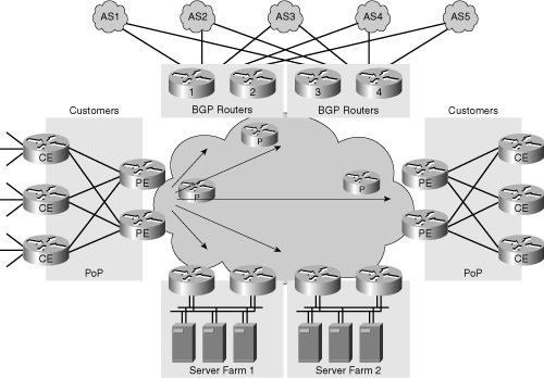
Figure 14-1 serves as the basis for this case study. It represents the different components of a service provider network from a high-level perspective:
Provider edge (PE) routers connected to the core network
Customer edge (CE) routers connected to the customers
Multiple points of presence (PoP) composed of PE and CE routers
Server farms or data centers
A core network connecting all the pieces to an intranet
Different BGP routers (numbered from 1 to 4) for the Internet connections via different providers and the BGP Autonomous Systems (AS) (displayed by AS1 through AS5).
Figure 14-1. Network Blueprint
[View full size image]


