Voice Performance Measurement
Measuring voice performance is fundamental for delivering voice services. From a user perspective, the service quality aspects of e-mail delivery and Internet surfing are nice to have. In a voice environment, quality of service (QoS) is a requirement from day one. As human beings, we are used to a certain voice quality from direct (that is, face-to-face) conversations, and we expect similar voice quality over the phone as well. In the absence of this quality, we tend to hang up the phone and use alternative telephony services such as cell phones, if available. Therefore, voice performance management needs to be considered before metering accounting records becomes relevant.
Standards and Technology
Several standards exist for metering voice performance. The following are relevant for gathering standard compliance data:
ITU-T standards:
- P.800 is the Mean Opinion Score (MOS).
- G.113 is the Impairment/Calculated Planning Impairment Factor (ICPIF), which measures transmission impairments by defining a loss/delay busy out threshold. G.113 was superseded by G.107 (E-Model).
- G.114 is the network one-way transmission time recommendation:
0 to 150 ms is acceptable for most applications (toll quality).
150 to 400 ms is acceptable if the users are aware of it (best-effort quality, e.g. for free Internet calls).
>400 ms is unacceptable for most applications and users.
- Y.1541 (network performance objectives for IP-based services) defines six different QoS classes, where a one-way mouth-to-ear transmission time of 150 ms is suggested for voice applications.
- G.107 E-Model calculates and evaluates end-to-end connection voice quality.
- P.862 is Perceptual Analysis Measurement (PAMS) and Perceptual Evaluation of Speech (PESQ). These are metrics for voice quality measurement.
IETF standards from the IP Performance Metrics (IPPM) working group:
- RFC 2879, A One-Way Delay Metric for IPPM
- RFC 2680, A One-Way Loss Metric for IPPM
- RFC 2681, A Round-Trip Delay Metric for IPPM
Mean Opinion Scores (MOS)
The dilemma of measuring the quality of transmitted speech is that it is subjective to the listener. In addition, each VoIP transmission codec delivers a different level of quality. A common benchmark to determine voice quality is MOS. With MOS, a wide range of listeners have judged the quality of voice samples on a scale of 1 (bad quality) to 5 (excellent quality). Table 15-1 shows MOS ratings and their corresponding descriptions.
| Score | Quality | Description of Quality Impairment |
|---|---|---|
| 5 | Excellent | Imperceptible |
| 4 | Good | Just perceptible, but not annoying |
| 3 | Fair | Perceptible and slightly annoying |
| 2 | Poor | Annoying but not objectionable |
| 1 | Bad | Very annoying and objectionable |
As the MOS ratings for codecs and other transmission impairments are known, an estimated MOS can be computed and displayed based on measured impairments. The ITU-T calls this estimated value Mean Opinion Score–Conversational Quality, Estimated (MOS-CQE) to distinguish it from objective or subjective MOS values.
Note that the initial MOS measurement was based on the round-trip time (RTT) only. The Cisco IOS implementation takes RTT delay and packet loss into the MOS calculation. However, jitter is not yet included.
Impairment/Calculated Planning Impairment Factor (ICPIF)
ICPIF originated in the 1996 version of ITU-T Recommendation G.113. ICPIF attempts to quantify the impairments to voice quality that are encountered in the network. It is the sum of measured impairment factors minus a user-defined access advantage factor (A) that is intended to represent the user's expectations based on how the call was placed (for example, a mobile call versus a fixed line call). ICPIF values are expressed in a typical range of 5 (very low impairment) to 55 (very high impairment). ICPIF values numerically less than 20 are generally considered adequate.
ICPIF is calculated by the following formula:
ICPIF = Io + Iq + Idte + Idd + Ie – A
where:
Io— Impairment caused by nonoptimal loudness rating
Iq— PCM quantizing distortion impairment
Idte— Talker echo impairment
Idd— One-way delay impairment
Ie— Equipment impairment
A— An Advantage or expectation factor that compensates for the fact that users may accept quality degradation, such as with mobile services
The Delay Impairment Factor (Idd) is a number based on the measured one-way delay. The original G.113 definition was superseded by G.107. The G.107 table is used as a lookup table for the measured delay to compute the Idd value. For example, a delay of 50 ms equals an Idd of 1.5, 200 ms equals an Idd of 7.4, and a 400-ms delay equals an Idd of 31.
The total one-way delay is the sum of the codec delay, look-ahead delay (from compression algorithms), one-way network delay, DSP processing delay, and receive jitter buffer playout delay.
The Equipment Impairment Factor (Ie) measures the distortion introduced by the codecs, related to the amount of measured packet loss. The percentage of packet loss results in a specific Ie factor per codec. For example, 4 percent packet loss equals an Ie factor of 12 for G.711 and 26 for G.729A.
Note
The Advantage factor considers the type of access and the user's expectation of quality for this particular service. A conventional wire line has a value of 0, whereas mobile service in a geographic area has a value of 10. The latest version of the ITU-T G.113 recommendation no longer includes the ICPIF model; instead, it refers implementers to the E-Model, described in ITU-T G.107. ICPIF is still a valid measurement approach, and not all management tools and features have implemented the E-Model yet.
Network Elements in the Voice Path
This section examines voice-related metering options that are available at the network elements. There are two fundamental approaches for leveraging device instrumentation for voice measurement: passive and active measurements. Passive measurement functions are available at voice components, such as the gateways; at metering devices, such as the Cisco Network Analysis Module (NAM); and at routers and switches, such as MIBs, NBAR, and NetFlow. Note that NetFlow offers more benefits from an accounting perspective; consequently, it is addressed in that section. IP SLA offers active measurement, which means that tests can be performed independently of existing voice traffic.
Passive Voice Performance Measurement
Cisco voice gateways calculate the ICPIF factor, which can be retrieved by polling the cvVoIPCallHistoryIcpif MIB object in the CISCO-VOICE-DIAL-CONTROL-MIB. If this value exceeds a predefined ICPIF threshold, an SNMP notification is generated. The call durations must be at least 10 seconds for the gateway to calculate the ICPIF value for the call.
Cisco IOS computation of the ICPIF value simplifies the formula and only takes the network components of ICPIF into account—the one-way delay impairment (Idd), the equipment impairment (Ie), and the advantage factor (A). The simplified IOS formula is ICPIF = Idd + Ie – A. Cisco Gateways use this formula to calculate the ICPIF for received VoIP data streams and Cisco IP SLA for VoIP operations.
One-way delay at the Cisco Gateway is calculated by dividing the MIB variable cvVoIPCallHistoryRoundTripDelay by a factor of 2. This variable is part of the callHistoryTable in the CISCO-VOICE-DIAL-CONTROL-MIB.
Because voice quality is measured only from the IP phone to the gateway, any unidirectional network QoS issues in the direction from the gateway to the IP phone are not included in the ICPIF calculation of the Cisco Gateway.
The NAM is a dedicated monitoring blade for the Catalyst 6000 and 4000 switches. A smaller NAM version for the Cisco 2600, 2800, 3660, 3700, and 3800 series access routers also exists. IP telephony-specific statistics are available, such as delay and jitter. The NAM can report VoIP protocols, including Skinny Client Control Protocol (SCCP), Real-time Transport Protocol (RTP), Real-Time Control Protocol (RTCP), Media Gateway Control Protocol (MGCP), H.323, and SIP. Note that RTCP is a subset of RTP.
Network-Based Application Recognition (NBAR) can also identify voice applications. With RTP Payload Type classification, NBAR looks for the RTP Payload Type field within the RTP header to identify voice and video bearer traffic. See Chapter 10, "NBAR," for more details on NBAR.
Active Voice Performance Measurement
Cisco IOS IP SLA uses synthetic traffic to measure performance between multiple network locations or across multiple network paths. It simulates VoIP codecs and collects network performance information, including response time, one-way latency, jitter, packet loss, and voice quality scoring. The following IP SLA operations are targeted toward VoIP measurement:
VoIP jitter
VoIP gatekeeper registration delay monitoring
VoIP call setup (post-dial delay) monitoring (H.323 or SIP)
RTP-based VoIP operation
The IP SLA VoIP UDP operation feature supports ICPIF, the transmission-rating factor R, and MOS values, but it does not support the E-Model. For more details on IP SLA, refer to Chapter 11, "IP SLA."
Cisco CallManager (CCM)
Cisco CallManager is an IP-based PBX that controls the call processing of a VoIP network. CCM is a central component in a Cisco Communication Network (CCN) system. A CCN comprises multiple regions, with each region consisting of several CallManager groups with multiple CallManagers.
CCM establishes voice calls and gathers call detail information in a VoIP environment. It generates records for each call placed to and from IP phones, conferences bridges, and PSTN gateways. Two different types of call records are produced:
Call Detail Records (CDR) store call connection information, such as the called number, the date and time the call was initiated, the time it connected, and the termination time. In addition, CDRs include call control and routing information.
Call Management Records (CMR) store information about the call's audio quality, such as bytes and packets sent or dropped, jitter, and latency. CMRs are also called diagnostic records. Voice quality trends can be discovered by inspecting the CDR's corresponding CMRs. The two records are linked by the GlobalCallID_callManagerId and GlobalCallID_Called fields in the CDR and CMR.
CCM generates a CDR when a call is initiated or terminated or if significant changes occur to an active call, such as transferring, redirecting, splitting, or joining a call. When diagnostics are enabled at the CCM, a CMR is stored for each call, separately for each IP phone involved or each MGCP gateway. The number of records written varies according to the type of call and the call scenario. For example, two CMRs occur for a call between two IP phones, and multiple CMRs are created in case of a conference call or videoconference. CDRs and CMRs are stored in the subscriber SQL database.
Note
CCM disables CDR generation by default. You can enable and disable CDRs without restarting the system.
Tables 15-2 and 15-3 describe a selection of CDR and CMR fields. For a list of all fields, see the latest CCM documentation on CCO.
| Field Name | Description |
|---|---|
| globalCallID_callManagerId | Designates a unique Cisco CallManager identity. |
| globalCallID_called | Designates a unique call identity value that is assigned to each call. |
| origLegCallIdentifier | Identifies a call's originating leg. |
| dateTimeOrigination | The date and time when the user goes off hook or the date and time when the setup message is received for an incoming call. UTC specifies the time. |
| origNodeId | Identifies the node to which the call's originator is registered at the time the call is made. |
| origIpAddr | Identifies the IP address of the device that originated the call signaling. |
| callingPartyNumber | For incoming calls, this field specifies the number of the calling party. |
| origMediaTransportAddress_IP | Identifies the IP address of the device that originated the medium for the call.
For Cisco IP phones, this field specifies the address of the Cisco IP phone. For PSTN calls, this field specifies the gateway's address. |
| destLegIdentifier | Identifies the terminating leg of a call. |
| destNodeId | Identifies the node within a cluster to which the call's terminating party is registered at the time the call is made. |
| destIpAddr | Identifies the IP address of the device that terminated the call signaling. |
| dateTimeConnect | Identifies the date and time that the call connected. UTC specifies the time. |
| dateTimeDisconnect | Identifies the date and time when the call was cleared. This field gets set even if the call never connected. |
| duration | Identifies the difference between the connect time and disconnect time. This field specifies how long the call remains connected, in seconds. This field remains 0 if the call never connected or was connected for less than 1 second. |
| origDeviceName | Specifies a text string that identifies the name of the originating device. |
| destDeviceName | Specifies a text string that identifies the name of the destination device. |
| destConversationID | Specifies a unique identifier that is used to identify the parties of a conference call. |
| Field Name | Description |
|---|---|
| cdrRecordType | Specifies the type of this specific record:
0: Start call detail record (not used) 1: End call detail record 2: CMR (default) |
| globalCallID_callManagerId | Designates a unique Cisco CallManager identity. |
| globalCallID_callId | Designates a unique call identity value that is assigned to each call. |
| callIdentifier | Specifies a call leg identifier that identifies the call leg to which this record pertains. |
| directoryNumber | Specifies the directory number of the device from which these diagnostics were collected. |
| dateTimeStamp | Represents the approximate time that the device went on hook. |
| numberPacketsSent, numberPacketsReceived | Designates the total number of RTP data packets the device transmitted (send, receive) since starting transmission on this connection. |
| numberOctetsSent, numberOctetsReceived | Specifies the total number of payload octets (excluding header or padding) that the device transmitted (send, receive) in RTP data packets since starting transmission on this connection. |
| numberPacketsLost | Designates the total number of RTP data packets that have been lost since the beginning of reception. This number designates the number of packets that were expected, less the number of packets that were actually received, where the number of packets that were received includes any that are late or duplicates. Thus, packets that arrive late are not counted as lost. |
| jitter | Provides an estimate of the statistical variance of the RTP data packet interarrival time, measured in milliseconds. RFC 1889 contains detailed computation algorithms. |
| latency | An estimation of the network latency, expressed in milliseconds. This value represents the average value of the difference between the NTP time stamp that the RTP Control Protocol (RTCP) messages indicate and the NTP time stamp of the receivers, measured when these messages are received. |
Cisco CallManager supports administrators to monitor their IP telephony environment. A web-based tool called Serviceability provides multiple functions. From a performance and accounting perspective, the following are relevant:
Real-Time Monitoring Tool (RTMT) displays real-time monitoring of the components in a Cisco CallManager cluster, such as device discovery and status, call activities, and system and services performance. RTMT continuously monitors a set of management objects, generates daily reports, and sends alerts if values breach thresholds. RTMT is a Microsoft Windows-based application that is installed at the client PC. Figure 15-2 shows a report from RTMT. The summary screen shows the main server parameters (memory and CPU usage) in conjunction with the number of registered phones, number of calls in progress, and active gateway ports and channels. A drilldown function offers comprehensive details.
Figure 15-2. Cisco CallManager RTMT Report
[View full size image]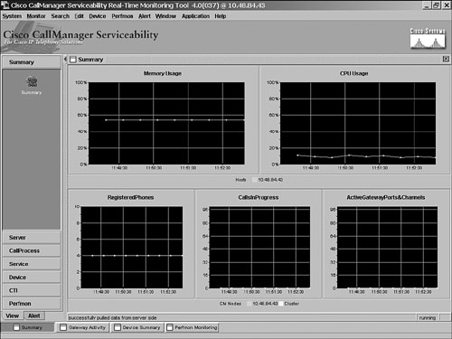
Quality Report Tool (QRT) provides voice quality and general problem reporting for Cisco IP Phones. QRT combines input from the various collection sources and displays the results with the QRT Viewer application:
- Information collected from the source device, such as IP address, codec, number of packets, jitter, and packets lost. QRT collects streaming data only once per call.
- Information collected from the destination device. It's the same as just described if the destination device is also a Cisco IP phone within the same CallManager cluster. Otherwise, this information includes only the IP address, device name, and device type.
- Information collected from the Cisco CallManager includes the source device name (MAC address), calling and called party number, CallManager ID, and call state.
- Information collected from the Real-Time Information Server (RIS), which maintains CallManager details such as source device type, model, and user. RIS also provides an interface for the CallManager SNMP Agent.
CDR Analysis and Reporting (CAR) generates reports for quality of service, traffic, and billing information from CDRs and CMRs:
- User reports, such as individual and department bills; Top-N reports by charge, duration, and number of calls
- System reports, such as QoS by gateway and call type, traffic summary, system overview, and CDR errors
- Device reports, such as utilization by gateway, route group, route list, route pattern, conference bridge, and voice mail
- CDR search functions to verify the details of a call in the CDR database and to track the quality of a call leg
Figure 15-3 shows a Cisco CallManager CAR report.
Figure 15-3. Cisco CallManager CAR Report

In addition to the reporting tools, Cisco CallManager includes an SNMP agent that provides detailed information about connected devices via the CallManager MIB (CISCO-CCM-MIB). The MIB contains phone tables and counters, and CallManager and other applications can use it to present provision and statistical information.
Besides the server-based Cisco CallManager, a software feature called Cisco CallManager Express (CCME) is implemented in Cisco IOS. CCME is an optional software feature that enables Cisco routers to deliver PBX functionality for enterprise branch offices or small businesses. The related MIB is the Cisco CallManager Express MIB (CISCO-CCME-MIB), which provides a comprehensive set of functions related to configuration, monitoring, and notifications.
Application Examples
In addition to the Cisco CallManager reporting functionality, two other applications are relevant: the integrated web reports of the Cisco NAM and the CiscoWorks Unified Service Monitor.
Network Analysis Module
The Catalyst NAM Traffic Analyzer provides a comprehensive set of voice reports:
Voice protocol overview— The "Aggregate Statistics" table contains basic troubleshooting information for the voice protocols, such as number of calls monitored, average and worst packet loss, and jitter.
Worst-quality calls— This table displays the Top-N worst calls based on packet loss and jitter.
Known phones— This table gathers details for a specific phone (SSCP or H.323), including the phone number, the phone details, aggregated statistics, and Last-N calls.
Active calls— This table displays information for all calls currently being monitored by the NAM.
Packet loss is included in the reports. If the NAM is located at the data center, in most cases it does not analyze the VoIP packets between the sender and receiver. Instead, the call setup and communication statistics messages are monitored. Therefore, the NAM should be placed near the Cisco CallManager (as opposed to being in the path between the caller and receiver) to intercept the CMR.
Figure 15-4 shows a NAM phone details report.
Figure 15-4. Cisco NAM VoIP Report

CiscoWorks Unified Operations Manager
CiscoWorks Unified Operations Manager provides a set of functions required to monitor VoIP network components, such as IP phones, gateways, Cisco CallManager, and Cisco Contact Center. Figure 15-5 shows the service level view.
Figure 15-5. CiscoWorks Unified Operations Manager Service Level View

CiscoWorks Unified Service Monitor is one component of the Cisco Unified Operations Manager. It evaluates voice performance metrics for calls in a VoIP network. The product consists of two elements: a hardware sensor and a software application. The Cisco 1040 sensor monitors voice-specific RTP data streams. It behaves similarly to a Cisco IP phone: it uses either the IEEE or Cisco Power over Ethernet (PoE), retrieves configuration information from a TFTP server, and it uses SCCP to communicate with the Service Monitor application. Figure 15-6 shows a sensor report from the Service Monitor.
Figure 15-6. CiscoWorks Unified Service Monitor Sensor Report

The sensor should be installed on a switch next to the IP phones that are being monitored. It captures RTP data streams based on voice codecs, analyzes them, and generates a MOS based on the ITU-T G.107 standard. The calculation occurs every 60 seconds. The quality metrics reporting to the server are through Syslog messages. The server application optionally summarizes the voice quality metrics and stores them in a data file for subsequent analysis and reporting. Reported MOS values are evaluated against a user-defined threshold. In case of a threshold violation, an SNMP trap can be sent to a fault or performance management application.


