Open Shortest Path First (OSPF) Between PE- and CE-routers
The last (currently available) PE-to-CE connectivity option to consider is the use of the Open Shortest Path First (OSPF) protocol. This option may be desirable to customers who already run OSPF within each of their sites and still want to exchange routing information between these sites using this protocol, without having to redistribute OSPF information into other protocols such as BGP-4 or RIP Version 2. If the MPLS/VPN backbone is used to connect the sites, then redistribution is not a requirement as the backbone links may be used for traffic, even if "back-door" links exist between the VPN sites, because the routes are viewed as inter-area rather than external.
The desire to restrict the amount of redistribution can be extremely important in an OSPF environment. Whenever a route is redistributed into OSPF, it is done so as an external OSPF route. The OSPF protocol dictates that external routes must be flooded across the whole OSPF domain, which increases the overhead of the protocol as well as the CPU load on all routers participating in the OSPF domain. To try to overcome this, certain area types, such as stub or totally stubby areas, can be deployed so that external routes are not sent into the area. However, this can have the drawback of sub-optimal routing because the area does not have the full topology information to make a decision on the best exit point toward the OSPF backbone for a particular external route.
Using the VPN overlay model, service providers have been capable of providing the infrastructure that can be used for the exchange of routing information between VPN customer sites. With this model, customer site routers form routing adjacencies with other site routers across Frame Relay/ATM virtual circuits and then directly exchange IP prefix information between CE-routers across these adjacencies using the OSPF protocol. With the introduction of an MPLS/VPN backbone, and hence a peer-to-peer VPN model, the exchange of site routing information becomes a challenge: Direct adjacencies between sites can no longer be formed because no direct virtual circuits exist. This means that a further mechanism is required to allow OSPF to function in this environment and to provide a seamless integration of OSPF sites into the MPLS/VPN infrastructure.
The goal of this enhancement must be to provide the same functionality within OSPF (from a customer's perspective) as seen when the overlay model is deployed, except that this functionality is provided through use of the peer-to-peer VPN model. This means that all internal VPN customer routes that belong to the same OSPF domain must be seen as either intra-area (LSA type 1 or type 2) or inter-area (LSA type 3) routes, and all external routes must be seen as either LSA type 5 or LSA type 7 routes.
Note
In topologies where the overlay model was previously used within the customer site, support of the OSPF protocol on the PE-to-CE link may actually reduce the complexity of a VPN customer's OSPF deployment. This will depend on how the overlay model was previously used.
In the case of point-to-point links, where multiple sub-interfaces are necessary between site routers, these links are no longer required with the introduction of MPLS/VPN because the CE-router will form a point-to-point adjacency with the PE-router. This means smaller interface configuration and fewer adjacencies for the OSPF protocol. It also implies less flooding in the event of a route change within the OSPF domain because fewer links exist within the topology.
In the case where non-broadcast multi-access (NBMA) is deployed, whether broadcast or non-broadcast, careful selection of the OSPF designated router (DR) and backup designated router (BDR) is necessary. However, with the introduction of MPLS/VPN, the PE-to-CE link will, in most cases, become a point-to-point link. Therefore, manipulation of the OSPF priority is no longer necessary because no designated router will exist. In the case where different sites are connected to the same PE-router across an NBMA network, then manipulation of the OSPF priority may still be a requirement.
The routing information learned from customer sites via OSPF is placed into the VRF that is associated with the incoming interface. This is exactly the same mechanism as is used for the other PE-to-CE connectivity options that we have already seen. These routes are then advertised across the MPLS/VPN backbone between PE-routers using MP-iBGP and are imported into relevant VRFs on other PE-routers.
To support PE-to-CE OSPF connectivity in an MPLS/VPN environment, an additional level of routing hierarchy is required for VPN sites to run independent OSPF processes and learn routes from other sites without a direct adjacency. The OSPF protocol already provides two levels of hierarchy: the backbone area 0 and any attached areas. A third level of hierarchy is provided so that we can connect sites within an MPLS/VPN backbone topology. This extra level of hierarchy is on top of area 0 (if area 0 exists).
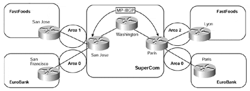
Multiple OSPF area 0s are possible with this type of configuration, and each site may choose to run an independent area 0. However, it is mandatory that any site area 0 be attached directly with the MPLS/VPN backbone so that a partitioned area 0 topology is avoided. Based on this, two different topologies can be used?one that connects sites that utilize an area 0, and one for sites that do not. Both of these topologies are illustrated in Figure 10-4.
Figure 10-4. PE-to-CE Connectivity?OSPF Topology Choices

We can see from Figure 10-4 that both the FastFoods and EuroBank VPN customers are running OSPF with the SuperCom MPLS/VPN backbone, but each customer is using a different connectivity option.
The FastFoods VPN sites are attached to the MPLS/VPN backbone through their respective areas, and no area 0 is used at either site (Option 1).
The EuroBank VPN sites each run an OSPF area 0 that includes their PE-to-CE link with the SuperCom backbone (Option 2).


