Virtual Private Network Evolution
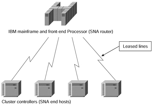
Initial computer networks were implemented with two major technologies: leased lines for permanent connectivity and dial-up lines for occasional connectivity requirements. Figure 7-1 shows a typical network from those days.
Figure 7-1. Typical Computer Network from 15 Years Ago

The initial computer network implementation provided the customers with good security (capturing data off leased lines requires dedicated equipment and physical access to the wires), but did not provide cost-effective implementation due to two reasons:
The typical traffic profile between any two sites in a network varies based on the time of day, the day of the month, and even the season (for example, traffic at retail stores increases around Christmas season).
The end-users always request fast responses, resulting in a high bandwidth requirement between sites, but the dedicated bandwidth available on the leased lines is used only part of the time (when the users are active).
These two reasons prompted the data communication industry and service providers to develop and implement a number of statistical multiplexing schemas that provided the customers with a service that was almost an equivalent to leased lines. This service was cheaper, however, due to the statistical benefits the service provider could achieve from a large customer base. The first virtual private networks were based on such technologies as X.25 and Frame Relay, and, later, SMDS and ATM. Figure 7-2 shows a typical VPN built with these technologies (for example, Frame Relay).
As you can see in Figure 7-2, the overall VPN solution has a number of components:
The service provider is the organization that owns the infrastructure (the equipment and the transmission media) that provides emulated leased lines to its customers. The service provider in this scenario offers a customer a Virtual Private Network Service.
Figure 7-2. Typical Frame Relay Network

The customer connects to the service provider network through a Customer Premises Equipment (CPE) device. The CPE is usually a Packet Assembly and Disassembly (PAD) device that provides plain terminal connectivity, a bridge, or a router. The CPE device is also sometimes called a Customer Edge (CE) device.
The CPE device is connected through transmission media (usually a leased line, but could also be a dial-up connection) to the service provider equipment, which could be an X.25, Frame Relay, or ATM switch, or even an IP router. The edge service provider device is sometimes called the Provider Edge (PE) device.
The service provider usually has additional equipment in the core of the service provider network (also called the P-network). These devices are called P-devices (for example, P-switches or P-routers).
A contiguous part of the customer network is called a site. A site can connect to the P-network through one or several transmission lines, using one or several CPE and PE devices, based on the redundancy requirements.
The emulated leased line provided to the customer by the service provider in the overlay VPN model (see the section, "Overlay and Peer-to-peer VPN Model," later in this chapter for more details) frequently is called a Virtual Circuit (VC). The VC can be either constantly available (Permanent Virtual Circuit [PVC]) or established on demand (Switched Virtual Circuit [SVC]). Some technologies used special terms for VCs, for example Data Link Connection Identifier (DLCI) in Frame Relay.
The service provider can charge either a flat rate for the VPN service, which normally depends on the bandwidth available to the customer, or a usage-based rate, which can depend on the volume of data exchanged or the duration of data exchange.
Modern Virtual Private Networks
With the introduction of new technologies in the service provider networks and new customer requirements, the VPN concept became more and more complex. Vendors introduced different and often conflicting terms, which further increased the complexity. The modern VPN services thus can span a variety of technologies and topologies. The only way to cope with this diversity is to introduce VPN classification, which you can do using four criteria:
The business problem a VPN is trying to solve. The major classes of business problems are intracompany communication (lately, also called intranet), inter-company communication (also called extranet), and access for mobile users (also called Virtual Private Dialup Network).
The OSI layer at which the service provider exchanges the topology information with the customer. Major categories here are the overlay model, where the service provider provides the customer with only a set of point-to-point (or multipoint) links between the customer sites, and the peer model, where the service provider and the customer exchange Layer 3 routing information.
The Layer 2 or Layer 3 technology used to implement the VPN service within the service provider network, which can be X.25, Frame Relay, SMDS, ATM, or IP.
The topology of the network, which can range from simple hub-and-spoke topology to fully meshed networks and multilevel hierarchical topologies in larger networks.


