Introduction of Route Reflector Hierarchy
The term route reflection is used to describe the operation of a BGP speaker advertising a route that was learned through an iBGP session to another iBGP peer. This practice is prohibited in normal BGP operation because the traditional BGP routing protocol had no safeguards against routing loops within an autonomous system (thus requiring a full mesh of iBGP speakers). A BGP speaker that propagates iBGP routes to other iBGP peers is called a route reflector, and such a route is called a reflected route.
With the introduction of route reflectors, the scaling of the MP-iBGP sessions becomes easier because the full-mesh requirement is eliminated. However, there will always be a finite number of sessions that can be made to the route reflector, so a hierarchical structure of route reflectors may be desirable; the design of the network should be capable of catering to its introduction. The actual number of sessions that a route reflector can service without affecting its functionality or its capability to reflect routing information is difficult to judge. It depends on many factors, such as the number of routes per session, the use of peer groups, the CPU power, and the memory resources of the route reflector.
For these reasons, formal recommendations are few, and no recommendation can really replace good design testing before full implementation. However, one scenario, using an RSP2 on a 7500 series router in one of the major core sites of the Internet, showed that it was possible to carry full Internet routing (about 40,000 routes at the time) for approximately 75 iBGP neighbors and still keep a reasonable level of CPU utilization.
Note
It should be noted that with the introduction of more advanced processors on various Cisco Systems platforms, this number is likely to be far greater, even though the full Internet routing table is now approximately 80,000 routes. With the introduction of peer-group support on route reflector iBGP sessions, this number will increase even further.
Note
In a large network, where the number of iBGP sessions on route reflectors is expected to be very high, you could deploy a design in which the route reflector does not forward any user traffic, but serves only as a route propagation device. Such a router would commonly have only one interface, deserving the name "router-on-a-stick."
As new PE-routers are introduced and the amount of neighbors or routes increases, it is good practice for processor load and memory usage to be monitored so that an optimal configuration can be maintained. If memory and CPU usage continue to increase, measures such as increased memory, higher-performance routers, or more route reflectors should be introduced into the topology.
It is always a good idea to run more than one route reflector so that a redundant configuration is provided. However, in a large-scale environment, it may be necessary to run even more than two route reflectors to help scale the topology and also provide the capability for expansion in the future. With this in mind, a suitable topology might be as shown in Figure 12-7. This topology illustrates regional ISP points of presence (POPs) connected to one or multiple core POPs. It also shows the hierarchical route reflection techniques, but it is not meant to represent an exact topology that will suit all customer needs.
Figure 12-7. Hierarchical Route Reflection?Sample Topology
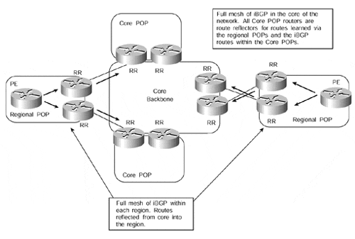
In Figure 12-7, we can see that the network can be split into separate route reflector clusters. Each router that is not a route reflector (in this case, any routers internal to the regional POPs) is required to peer to two separate route reflectors, each of which is either in a different cluster or within the same cluster.
Note
For a full discussion on route reflectors and route reflector clusters, refer to the Cisco press publication Internet Routing Architectures, Second Edition, written by Bassam Halabi.
Previously, it was not advisable for peer clients to separate route reflector clusters because of unnecessary route propagation, sometimes referred to as routing information loops. However, this restriction was lifted, and the BGP selection process was changed so that the chances of a routing information loop were reduced considerably. However, it is still considered to be a good design practice for a BGP router to be peered only with route reflectors in the same cluster.
Note
The definition of a routing information loop is the unnecessary propagation of routing information, thus causing duplication of routing information. This is not the same as a routing loop, in which the information contained within the routing table of a particular device differs from another device, potentially causing a "ping-pong" effect of packets entering a loop between the two devices.
The route reflectors within the core of the network are peered together in a full iBGP mesh. This means that any information received from a client (the clients, in this case, are the regional POP route reflectors) by a route reflector within the core will be advertised into the other clusters via the full iBGP mesh between the route reflectors. This type of configuration provides redundancy in case one of the route reflectors fails or the path to this route reflector becomes unavailable. It also potentially provides geographic redundancy where each of the route reflectors is in a physically different location to the other.
Note
If more than one route reflector exists within a cluster, it is mandatory for all clients to peer with all the route reflectors within the cluster. If one client does not have all these peerings, then it is possible that the BGP information will be partitioned within the cluster.
Route Reflection of PE Routes to Aid Scaling
Although Figure 12-7 provides a good hierarchical and scalable route reflection design, in many cases, this type of topology will not be available or even required. In a standard, large-scale ISP design in which external routing information is required within the core of the network, this topology is certainly appropriate. It may also be appropriate if there is a requirement to send VPN-IPv4 routes between PE-routers within each region and across regions, or if the size of the MPLS/VPN backbone dictates that multiple route reflectors be deployed to help scale the topology.
However, with the introduction of the MPLS-enabled VPN service, our real requirement is the propagation of external routing information between PE-routers. This information should not be necessary within the core of the network unless our core routers are acting as route reflectors between regional sites, as in the example shown in Figure 12-7. This means that dedicated route reflectors may be deployed; the number of these will depend on the topology and size of the backbone network, as well as on how the reflection of routes between VPNs is performed. The level of redundancy for route reflection must also be considered, along with the geographical distribution of the BGP peering sessions, so that intraregional connectivity can be maintained in the event of a link failure from the region into the backbone.
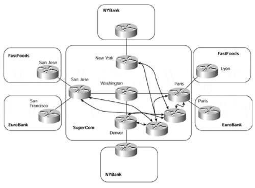
To achieve this type of topology, we have some choices on how to reflect routes between the PE-routers. Our first choice is to deploy a number of router reflectors and then peer all PE-routers to these route reflectors. This type of topology can be seen in Figure 12-8. For the sake of simplicity, only two route reflectors are shown.
Although this type of topology achieves our objective of route reflection between PE-routers, and although all PE-routers are capable of learning VPN routes from other PE-routers, some PE-routers will receive routes for a particular VPN for which they have no members. An example of this is the San Jose PE-router. It will receive VPN routes for the NYBank VPN, but it does not have any attached customers that belong to that VPN. This means that the routes will be dropped through use of the automatic route filtering feature that we described in Chapter 9.
Note
It is important to understand that whenever route reflectors are deployed, there is a danger that the route reflector may select a best path that is different than the best path that would have been selected by a client if it had been fully meshed. Although this does not cause a problem in forwarding traffic, it may introduce some suboptimal routing if the chosen best path is not the closest exit point from a client's point of view. This is because the scope of route reflectors is to reduce the iBGP session requirement without having any impact on the packet forwarding scheme.
Figure 12-8. Introduction of Route Reflection for MP-iBGP
Route Reflector Partitioning
To try to overcome the unnecessary advertisement of routes to PE-routers that do not import them, we need to filter routing information at some point in the network before this information is advertised across any MP-iBGP sessions. This filtering could be achieved through mechanisms such as access lists, or it could be achieved through careful layout of the topology.
If the careful layout of the topology approach is taken, then our main objective is to split the network into multiple route reflector clusters, each servicing a certain number of VPNs. The PE-router clients of these route reflectors will then receive only routes that belong to the relevant VPNs that they service. We will see in the sections that follow that we can achieve this objective in several ways.
Our first deployment option is to split up the topology of the network so that PE-routers peer only with certain route reflectors and each PE-router services only certain VPNs. This technique is illustrated in Figure 12-9.
Figure 12-9. Partitioning Route Reflectors Between PE-routers
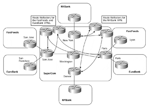
Although this approach enables us to partition the route reflection, it does not provide us with an easily adapted solution if we want to add a different VPN to an existing PE-router in the future. If we consider a situation in which an existing PE-router suddenly needs to service a VPN to which it has not provided routes previously, we would need to change the PE-router configuration. This configuration change would be necessary so that a further session to another route reflector (one that serviced the new VPN) could be obtained, to somehow filter the routes so that we sent routes only to the correct route reflectors.
If we examine the topology in Figure 12-9, we can see that if the San Jose PE-router wants to join the NYBank VPN at some point in the future, we will need to make several configuration changes. The first change would be to configure an MP-iBGP session from the San Jose PE-router to the route reflector that services the NYBank VPN. When this session configuration has been added, filters would need to be added to prevent the San Jose PE-router from sending any routes from the FastFoods or EuroBank VPNs toward the NYBank VPN route reflector, and also from sending any NYBank VPN routes to the FastFoods or EuroBank VPN route reflector. There are obvious drawbacks to this approach, such as the configuration and management overhead.
Standard Community Filtering on PE-routers
Our requirement to filter routes before advertisement from a PE-router can be achieved through the use of standard BGP communities. This provides us with the capability to partition the route reflectors. Instead of relying on topology or extensive access lists to filter the routes, however, we can now rely on filtering based on the community value. In doing so, we are easily able to add a new VPN to an existing PE-router and just configure a session to the relevant route reflector.
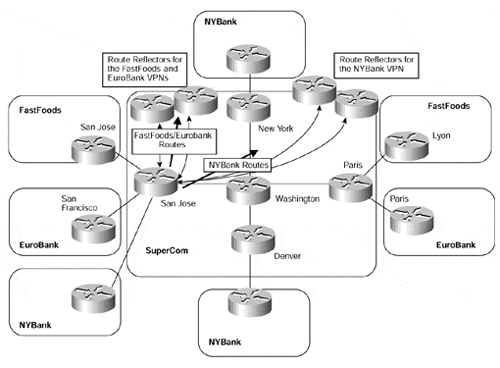
With this method, we must assign a separate standard BGP community for each VRF (this could be the same as the route target, as long as its format is not extended). We also must apply outbound route filtering, based on the BGP community, when the routes from the VRF are advertised toward the route reflectors. This enables us to send only certain VPN routes to selected route reflectors so that any PE-router that has a session with the route reflector will receive the routes. This technique is demonstrated in Figure 12-10, and the relevant route target and standard BGP communities are shown in Table 12-5. This example is similar to the one in Figure 12-9; in this case, however, the San Jose PE-router needs to service all VPNs, so it has sessions to several route reflectors. For the sake of simplicity, only the San Jose PE-router MP-iBGP sessions are shown in the figure.
In our previous example, we would need to apply extensive filtering to the San Jose router to achieve our goal. However, the difference now is that each PE-router is capable of peering to multiple route reflectors and sending only the relevant routes for each VPN based on the standard BGP community value.
|
VPN Name |
Route Target |
Standard Community Value |
|---|---|---|
|
FastFoods |
100:26 |
100:26 |
|
EuroBank |
100:27 |
100:27 |
|
NYBank |
100:28 |
100:28 |
Figure 12-10. Standard Community Filtering Toward Route Reflectors
Note
In Table 12-5, the same value has been used for the route target and the standard BGP community value. This is because, in this example, the value of the route target is not extended and therefore can be used for the standard community as well as the extended community. Each attribute uses a different attribute type value, so they may use the same value; they are not comparable by the BGP process.
The configuration for the San Jose PE-router shown in Figure 12-10 can be seen in Example 12-7. The FastFoods/EuroBank route reflector has a BGP peering address of 194.22.15.5/32, and the NYBank route reflector has an address of 194.22.15.6/32 (per Table 12-1).
Example 12-7 Standard Community Filtering Toward Route Reflectors
interface loopback 0

 ip address 194.22.15.2 255.255.255.255

!

ip vrf FastFoods

 rd 1:26

 route-target both 100:26

!

ip vrf EuroBank

 rd 1:27

 route-target both 100:27

!

ip vrf NYBank

 rd 1:28

 route-target both 100:28

!

router bgp 1

 neighbor 194.22.15.5 remote-as 1

 neighbor 194.22.15.5 update-source loopback0

 neighbor 194.22.15.6 remote-as 1

 neighbor 194.22.15.6 update-source loopback0

!

address-family ipv4 vrf FastFoods

 neighbor 195.12.2.6 remote-as 100

 neighbor 195.12.2.6 activate

 neighbor 195.12.2.6 route-map FastFoods_routes_in in

exit address-family

!

address-family ipv4 vrf EuroBank

 neighbor 10.2.1.6 remote-as 150

 neighbor 10.2.1.6 activate

 neighbor 10.2.1.6 route-map EuroBank_routes_in in

exit address-family

!

address-family ipv4 vrf NYBank

 neighbor 196.27.6.6 remote-as 200

 neighbor 196.27.6.6 activate

 neighbor 196.27.6.6 route-map NYBank_routes_in in

exit address-family

!

address-family vpnv4

 neighbor 194.22.15.5 activate

 neighbor 194.22.15.5 send-community extended

 neighbor 194.22.15.5 route-map FastFoods_EuroBank_routes_out out

 neighbor 194.22.15.6 activate

 neighbor 194.22.15.6 send-community extended

 neighbor 194.22.15.6 route-map NYBank_routes_out out

exit address-family

!

ip community-list 1 permit 100:26

ip community-list 2 permit 100:27

ip community-list 3 permit 100:28

!

route-map FastFoods_routes_in permit 10

 set community 100:26

!

route-map EuroBank_routes_in permit 10

 set community 100:27

!

route-map NYBank_routes_in permit 10

 set community 100:28

!

route-map FastFoods_EuroBank_routes_out permit 10

 match community 1

!

route-map FastFoods_EuroBank_routes_out permit 20

 match community 2

!

route-map NYBank_routes_out permit 10

 match community 3
Route Target Attribute-based Filtering on Route Reflectors
Although the previous example of standard community-based filtering provides a workable solution, it still requires configuration on each PE-router within the backbone so that only relevant routes are sent toward the route reflectors.
A different approach to this is to apply the filtering at the route reflector. With the introduction of route target-based control of VPN-IPv4 prefixes serviced by a route reflector, it is possible to limit the number of prefixes that the route reflector has to manage. This is achieved by specifying which route targets should be accepted by the route reflector for reflection to PE-clients.
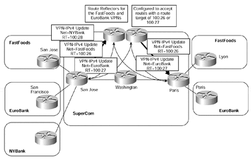
We have already described that a route reflector will not currently filter any routes by default (although, as will be seen later in this chapter, this will change with the use of the bgp rr-group command). This means that configuration is needed to allow for certain routes to be filtered. This can be achieved again through the use of route maps. Figure 12-11 shows an example of the FastFoods/EuroBank route reflector cluster.
With this feature, it is no longer necessary to configure each PE-router with standard communities so that outbound filtering toward the route reflector will occur. In addition, you could have multiple sessions to different route reflectors and let the route reflector take care of VPN-IPv4 prefix filtering and the correct advertisement of the routes to all relevant PE-routers within the MPLS/VPN domain. Example 12-8 shows the configuration of one of the route reflectors from Figure 12-11.
Figure 12-11. Route Reflector Filtering Using Route Target
Example 12-8 Route Reflector Extended Community Filtering Configuration
router bgp 1

 no bgp default ipv4-unicast

 neighbor 194.22.15.2 remote-as 1

 neighbor 194.22.15.2 update-source Loopback0

 neighbor 194.22.15.1 remote-as 1

 neighbor 194.22.15.1 update-source Loopback0

 !

 address-family vpnv4

 neighbor 194.22.15.2 activate

 neighbor 194.22.15.2 route-reflector-client

 neighbor 194.22.15.2 send-community extended

 neighbor 194.22.15.2 route-map RTfilter in

 neighbor 194.22.15.1 activate

 neighbor 194.22.15.1 route-reflector-client

 neighbor 194.22.15.1 send-community extended

 exit-address-family

!

ip extcommunity-list 1 permit rt 100:26 rt 100:27

!

route-map RTfilter permit 10

 match extcommunity 1
Route Reflection and ORF Capability
Although the two previous examples have provided differing ways of filtering unwanted routing updates, both have drawbacks. In the case of standard community filtering on the PE-routers, the overhead of having to maintain multiple filters for each PE-router within the backbone is restrictive. In the case of route target filtering on the route reflectors, unwanted updates are sent toward only the route reflector to be filtered. Therefore, the ultimate solution would be to filter updates at the PE-routers so that they are not sent toward route reflectors that do not need them, but also to make this dynamic so that extensive filtering configuration is not necessary on the PE.
This solution is provided through use of the ORF capability that was described in Chapter 9. Using this capability, each route reflector is preconfigured with a list of route targets that it will accept for reflection to any PE-clients. All the PE-clients are treated as a single peer group, so the ORF capability is used to set the outbound filtering of the PE-client so that it does not send unwanted routes toward the route reflector. This is shown in Figure 12-12.
Figure 12-12. Route Reflection and ORF Capability
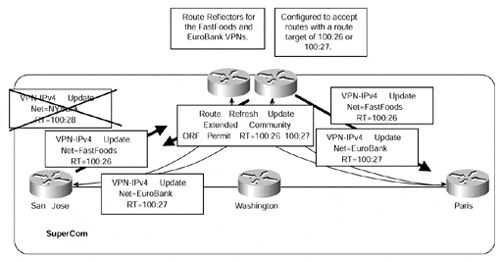
The functionality depicted in Figure 12-12 is automatic through configuration of an extended community list and route reflector group. Table 12-6 shows all the necessary commands for the route reflector configuration.
|
Step |
Command |
Purpose |
|---|---|---|
|
1 |
ip extcommunity-list extcommunity-list number |
This command provides the facility to set up an extended community list that specifies all the permitted route target attributes that will be referenced through the bgp rr-group command. |
|
2 |
bgp rr-group extcommunity-list number |
This command provides the facility to set up a route reflector group, which is similar in nature to a peer group. The extcommunity-list argument enables you to specify which extended community list should be used to indicate which routes, based on their route target, should be propagated through the ORF update to all PE-neighbors of the group. |


