Control-plane Connectivity Across an LC-ATM Interface
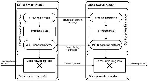
MPLS architecture requires that the control planes of adjacent LSRs have pure IP connectivity to exchange label binding as well as other control packets (for example, routing protocol hello packets and routing updates), as shown in Figure 3-2.
Figure 3-2. Information Exchange Between Adjacent LSRs

In Frame-mode MPLS, this requirement is easily met because the routers can send and receive IP packets as well as labeled packets over any Frame-mode interface, whether LAN or WAN. The ATM switches, however, do not have this capability.
There are two ways of guaranteeing pure IP connectivity between the ATM-LSRs:
Through an out-of-band connection, such as an Ethernet connection between the switches.
Through an in-band management VC, similar to the way that ATM Forum protocols (User-Network Interface [UNI] or Integrated Local Management Interface [ILMI]) are implemented. The detailed architecture of this solution is shown in Figure 3-3.
Note
The current LC-ATM IETF specification specifies only the in-band management VC, and the IOS implementation of MPLS on the ATM platforms implements only this method. The in-band management VC is also used for other control purposes, such as for IP routing protocol traffic.
Figure 3-3. MPLS Control Virtual Circuit Architecture

The MPLS control VC is by default configured on VC 0/32 and must use LLC/SNAP encapsulation of IP packets as defined in RFC 1483 (the corresponding IOS keyword is aal5snap).
MPLS Control-plane Connectivity in Cisco IOS Software
The control-plane connectivity in Cisco IOS software is established as soon as MPLS is configured on an ATM interface of a router or an ATM switch. The configuration mechanisms are slightly different, though:
On a router, you create an LC-ATM interface by configuring a separate ATM subinterface with the interface type tag-switching, as displayed in Example 3-1, and by configuring MPLS on that subinterface.
On a switch, you simply configure MPLS on an ATM interface, similar to the way that MPLS is configured on Frame-mode router interfaces, as displayed in Example 3-2.
Note
Configuration commands in Example 3-2 are valid only for IOS-based switches, including LightStream 1010, Catalyst 8510, and Catalyst 8540, but not the BPX series of switches.
Example 3-1 Configuring LC-ATM Interface in a Router
SanJose#configure terminal

SanJose(config)#interface atm 2/0/0.1 tag-switching

SanJose(config-if)#ip unnumbered loopback 0

SanJose(config-if)#tag-switching ip
Example 3-2 Configuring LC-ATM Interface in an IOS-based ATM Switch
SanFrancisco#configure terminal

SanFrancisco(config)#interface atm 2/1/3

SanFrancisco(config-if)#ip unnumbered loopback 0

SanFrancisco(config-if)#tag-switching ip
Note
It is highly recommended that you configure a loopback interface on every LSR to have a stable TDP/LDP LSR ID. The subnet mask of the loopback interface should be set to 255.255.255.255 to reduce the address space usage and to prevent undesired side effects when using OSPF as your routing protocol. The LC-ATM interfaces should be unnumbered and based on loopback interfaces. If multiple loopback interfaces will be used on the LSR, the TDP/LDP LSR ID should be explicitly configured using the tag-switching tdp router-id or mpls ldp router-id commands.
The status of an LC-ATM interface can be easily verified by using the show tag-switching interface detail command, similar to Example 3-3. The printout displays whether MPLS is enabled on an interface (IP tagging enabled) and whether the TDP/LDP session with a neighbor is already established (tagging operational). The printout also gives you the maximum MTU, the VPI/VCI value of the control VC, and the VPI range for label allocation.
Example 3-3 show tag-switching interface detail Command
SanFrancisco#show tag-switching interface detail

Interface ATM0/0/3:

        IP tagging enabled

        TSP Tunnel tagging not enabled

        Tagging operational

        MTU = 4470

        ATM tagging: Tag VPI = 1, Control VC = 0/32
Note
The VC used to exchange routing updates and TDP/LDP messages can also be displayed with the show atm vc command. Using this command to verify that the VC with the VPI/VCI value 0/32 is established is a good initial step in ATM MPLS troubleshooting. If this VC is not active, the interface is not working in LC-ATM mode.
Control-plane Implementation in an ATM Switch
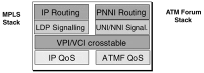
With the deployment of MPLS in the ATM-LSRs, the central processor of an ATM switch must support MPLS signaling and VC setup protocols in addition to the traditional ATM Forum signaling protocols such as UNI and PNNI. The two sets of protocols run transparently side by side, as shown in Figure 3-4. (This mode of operation is sometimes also called the ships-in-the-night approach.)
Figure 3-4. Signaling Protocols Running in an ATM Switch

In some ATM switches, the additional functionality required by the MPLS protocol stack can be implemented in the existing control processor of the switch. These ATM switches include LightStream 1010, Catalyst 8510, and Catalyst 8540 from Cisco Systems.
Other ATM switches cannot be directly upgraded with new firmware that would support MPLS. In these cases, an external MPLS controller can be added to the switch to support the additional functionality. The communication between the switch and the external controller supports only simple operations such as setting up a VC, and all the internode MPLS signaling is processed by the external controller.
Cisco Systems' implementation of an external controller is the Label Switch Controller (LSC) for the BPX family of ATM switches. The LSC attaches to the BPX through a standard ATM interface. The Virtual Switch Interface (VSI) protocol running between the LSC and the ATM switch supports the VC additions and deletions. All the higher-layer MPLS operations (exchanging routing updates, building routing tables, exchanging labels through TDP or LDP) are performed by the external controller that utilizes the control VC 0/32.


