VPN Customer Access into the MPLS/VPN Backbone
We have seen in previous chapters how VPN customer routes are propagated around an MPLS/VPN backbone network, through the use of MP-BGP. These routes are taken from VPN routing and forwarding instances (VRFs), with which customer sites are associated. The population of these forwarding tables is achieved through advertisement of VPN routes across the backbone network, as discussed in Chapter 9, "MPLS/VPN Architecture Operation," and also from the receipt of routing updates from attached customers (or through static routing).
There are currently four separate ways that an MPLS/VPN backbone can receive routes from a VPN customer CE-router: BGP-4, RIP Version 2, OSPF, and static routing. In the last chapter, we examined two of these options?namely, static routing and RIP Version 2. The last two options, BGP-4 and OSPF, will be examined in this chapter. We'll also review the design choices that are available using all four possible PE-to-CE connectivity options.
Note
Further options may become available over time, including the support of Enhanced IGRP and Intermediate System-to-Intermediate System (IS-IS).
Regardless of which protocol is used between the PE- and CE-routers, customer VPN routes will be placed into the VRF that is associated with the interface to which the CE-router is attached. This requires that the routing protocol processes that run on the PE-router be configured so that any routing information learned from this interface can be associated with a particular VRF. We saw in the previous chapter that this is achieved through the standard routing protocol process, either as a separate process or as a routing context within the process. A separate routing context, or process, is used per VRF.
When the VRF has been populated with any routes, these routes must be advertised across the MP-iBGP sessions to other PE-routers as VPN-IPv4 (also referred to as VPNv4) prefixes. To allow this to happen, a representation of the routing context must be configured within the BGP process configuration to tell BGP which VRF routes to advertise. We saw in the previous chapter that this is achieved through the use of address families and the redistribution of routes from a particular routing context, or process, into MP-iBGP.
The redistribution of routes into MP-iBGP is necessary only when the routes are learned through any means other than BGP between the PE- and CE-routers. This includes connected subnets and static routes. In the case of routes that are learned via BGP from the CE-router, redistribution is not required because it is performed automatically, although the routing context and the BGP neighbors must be configured within the BGP process through use of an address family.
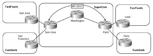
Again, a sample topology will be used throughout the first section of this chapter to assist in the explanation of the various connectivity options and their configuration. This sample topology can be seen in Figure 10-1, with all relevant address ranges for each VPN customer shown in Table 10-1.
Figure 10-1. PE-to-CE Connectivity Options?Sample Topology

|
Company |
Site |
Subnet |
|---|---|---|
|
FastFoods |
San Jose |
195.12.2.0/24 |
|
Lyon |
10.2.1.0/24 |
|
|
EuroBank |
San Francisco |
10.2.1.0/24 |
|
Paris |
196.7.25.0/24 |
|
|
SuperCom |
Paris (Loopback 0) |
194.22.15.1/32 |
|
San Jose (Loopback 0) |
194.22.15.2/32 |


