MPLS Loop Detection and Prevention
An important issue to consider when deploying the MPLS architecture is its capability to detect and prevent forwarding loops within the topology. A forwarding loop in an IP network is the process by which a router forwards a packet down the incorrect path (as far as its neighbor is concerned) to a particular destination based on the information contained in its routing table. This can happen during a convergence transition when dynamic routing protocols are used, or through the misconfiguration of the routers so that one router points to another router that is not actually the correct next-hop for a particular destination.
In terms of the MPLS architecture, you must consider both the control plane and the data plane, and how loop prevention is deployed in both a Frame-mode and Cell-mode backbone. You also must understand how each can detect, and deal with, forwarding loops.
Loop Detection and Prevention in Frame-mode MPLS
As shown in Chapter 2, labels are assigned to particular FECs using independent control mode when running MPLS across a Frame-mode implementation. When you use this mode, labels are assigned to FECs based on whether the FEC exists within the routing table of the LSR. Using these label assignments, you can establish Label Switched Paths (LSPs) across the MPLS network. Building on this knowledge, you can understand how each LSR can detect, and prevent, forwarding loops.
Frame-mode: Data Plane Loop Detection
In a standard IP-routed network, forwarding loops can be detected by examining the TTL field of an incoming IP packet. Using this field, each router in the packet's path decrements its value by 1; if the field reaches 0, the packet is dropped and the forwarding loop is broken. Figure 5-3 illustrates this mechanism.
Figure 5-3. Loop Detection Using TTL in an IP Network
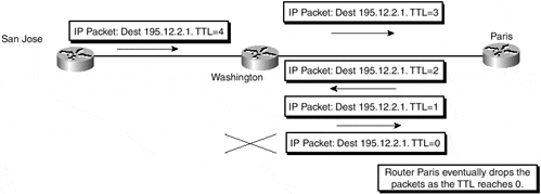
As Figure 5-3 shows, a loop has been formed between the Washington and Paris routers. Because each router decrements the TTL field by 1, the loop eventually is discovered and the looping packet is dropped (by the Paris router in the example). This same mechanism is used within the data plane of a Frame-mode implementation of MPLS. Each LSR along a particular LSP decrements the TTL field of the MPLS header whenever it forwards an incoming MPLS frame, and drops any packets that reach a 0 TTL.
Note
This also is true of an ATM interface that is not running MPLS directly with any ATM switches. This is because a PVC across this interface is treated as one hop, although it might traverse a series of ATM switches.
Frame-mode: Control Plane Loop Prevention
The detection of forwarding loops is obviously a very necessary function. However, it also is necessary that the LSR be capable of preventing these forwarding loops before they occur. This prevention activity must be achieved within the control plane because this is where Label Switched Paths (LSPs) are created.
In a standard IP-routed network, the prevention of forwarding loops is the job of the interior routing protocol. Because each LSR in a Frame-mode implementation of MPLS uses these same routing protocols to populate its routing table, the information that is used to form the LSPs within the network is the same as with a standard IP-routed network. For this reason, a Frame-mode implementation of MPLS relies on the routing protocols to make sure the information contained in the routing table of the LSR is loop-free, in exactly the same way as a standard IP-routed network.
Loop Detection and Prevention in Cell-mode MPLS
When you deploy MPLS across ATM switches and routers that run LC-ATM interfaces, the mechanisms used for loop detection and prevention in a Frame-mode deployment are not adequate for this type of environment. This is because there is no concept of TTL within an ATM cell header and a different method achieves the allocation and distribution of labels. Therefore, new mechanisms specific to the ATM environment are necessary so that MPLS can be deployed successfully across this type of network.
To see how the detection and prevention of loops is deployed within an ATM environment, consider both the MPLS control plane and the MPLS data plane to see how they differ from the Frame-mode implementation.
Cell-mode: Control Plane Loop Detection/Prevention
As discussed in Chapter 2, "Frame-mode MPLS Operation," when MPLS is deployed across LC-ATM interfaces and ATM switches, the control plane uses downstream-on-demand label distribution procedures with ordered label allocation by default. This means that the allocation and distribution of labels occurs based on request rather than on the presence of a particular FEC in the routing table of the ATM-LSR. You also saw that you can use independent label allocation on ATM-LSRs, which means that an ATM-LSR can allocate a label for each FEC independently of whether it already received a label mapping from a downstream ATM-LSR neighbor. In either case, a label request message is sent on demand to the downstream neighbor for a particular FEC to ask for a label mapping for that FEC. A significant difference exists between the two methods: When you use independent control mode, the ATM-LSR returns a label mapping immediately to the source of the label request message, whereas when you use ordered control mode, the ATM-LSR waits for a label mapping from its downstream neighbor before allocating and sending its own label mapping to the source of the label request message.
The consequence of both of these methods is that although the ATM-LSR still relies on the interior routing protocol to populate its routing table, it also must rely on the successful completion of signaling mechanisms to be able to create a Label Switched Path (LSP) to a particular FEC. To understand why this could be an issue, and why the control plane of MPLS running in Cell-mode has been enhanced, review how to achieve label distribution and allocation (using ordered control for simplicity), through the example shown in Figure 5-4.
Figure 5-4. Downstream-on-demand and Ordered Control Mode
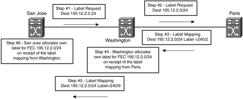
As you can see in Figure 5-4, when the San Jose ATM edge-LSR wants to set up an LSP to FEC 195.12.2.0/24, it checks its local routing table to find the next-hop for the FEC. After it determines this next-hop (by examining the LDP/TDP neighborship information), it can find which LDP/TDP neighbor has this next-hop as one of its directly connected interfaces. The San Jose ATM edge-LSR then sends a label request message to its next-hop downstream neighbor, the Washington ATM-LSR in the example. This label request message travels across the MPLS network, hop by hop, and eventually reaches the egress ATM-LSR for FEC 195.12.2.0/24, which is the Paris ATM-LSR in the example.
The Paris ATM-LSR sends a label mapping message upstream in response to the label request message, which cascades back down the LSP until reaching the ingress ATM-LSR. When this process is complete, the LSP is ready to pass traffic. This method works fine except that it is possible for either the label request or the label mapping messages to be forwarded continually between ATM-LSRs due to incorrect routing information. This is the same situation as in the previous TTL example, and it constitutes a forwarding loop of the control information. This certainly is undesirable, so extra mechanisms are necessary within the control plane to prevent this from happening.
Note
The possibility of a control information forwarding loop is apparent only when you deploy non?merge-capable ATM-LSRs. This is because an ATM-LSR becomes a merging ATM-LSR when it must merge at least two LSPs to the same FEC and it is configured to support VC merge. Therefore, when the first label request is received for a particular FEC, only one of the preceding conditions is met and non-merging ATM-LSR procedures are used. If both conditions are met, no further label request message is sent, regardless of whether a label mapping is received for the initial label request.
This mechanism is provided through the use of a hop-count TLV, which contains a count of the number of ATM-LSRs that the label request or label mapping message traversed. When an ATM-LSR receives a label request message, if it is not the egress ATM-LSR for the FEC contained within the message or does not have a label for the FEC, it initiates its own label request message and sends it to the next-hop ATM-LSR. This next-hop ATM-LSR again is determined by the analysis of the routing table.
Note
The current Cisco TDP implementation uses a hop-count object as part of the TDP label request and label mapping messages. This mechanism is the same as the LDP hop-count TLV that is specified in section 2.8, "Loop Detection" of draft-ieft-mpls-ldp, which is supported by the Cisco implementation of LDP.
If the original label request message contained a hop-count object/TLV, the ATM-LSR also includes one in its own label request message but increments the hop-count by 1. This is the inverse of the TTL operation, where the TTL is decreased by one although the same concept of a maximum number of hops is used. When an ATM-LSR receives a label-mapping message, if that message contains a hop-count object/TLV, this object/TLV hop-count is also incremented by 1 when the local label mapping is sent upstream.
When an ATM-LSR detects that the hop-count has reached a configured maximum value (254 in the Cisco implementation), it considers that the message has traversed a loop. It then sends a "Loop Detected Notification" message back to the source of the label request, or label mapping, message. Using this mechanism, a forwarding loop can be detected and subsequently prevented. Figure 5-5 illustrates this process.
Figure 5-5. Hop-count Object/TLV Processing
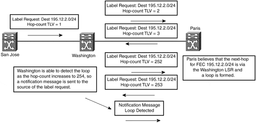
One problem with the hop-count method of loop detection is that potentially the time to discover the loop might be large based on the principle that the hop-count might need to increase to 254 before the loop is detected.
Note
The default hop-count within the Cisco implementation is 254 hops. You can change this, however, using the tag-switching atm maxhops command. Using this command, you can reduce the maximum number of hops, thus reducing the amount of time that potentially might be needed to detect a loop in the control information.
For this reason, draft-ietf-mpls-ldp provides a path vector mechanism through the use of the path-vector TLV, which can detect a loop based on the path that the message traversed. This is similar in concept to the way that BGP-4 detects loops within an AS_PATH, but in the case of MPLS, the LSR identifier is used. Using this mechanism, each ATM-LSR appends its LSR identifier to the path-vector list whenever it propagates a message that contains the path-vector TLV. If a message is received that contains the ATM-LSR's own LSR identifier within the path-vector list, the loop is detected and a "Loop Detected Notification" is sent back to the source of the message. Figure 5-6 shows this process.
Figure 5-6. Path-Vector TLV Loop Prevention Mechanism
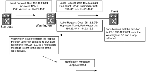
As Figure 5-6 shows, the LSR identifier of each ATM-LSR is added to the label request message as it proceeds through the network. Due to incorrect routing information, the Washington ATM-LSR believes that the next-hop for FEC 195.12.2.0/24 is via the Paris ATM-LSR, but the Paris ATM-LSR believes the next-hop for FEC 195.12.2.0/24 is via the Washington ATM-LSR. This constitutes a loop. The Washington ATM-LSR can detect this loop because it sees its own LSR identifier in the label request message.
Cell-mode??Data Plane Loop Detection
You learned already that an ATM cell header does not have any concept of TTL. This means that the mechanisms already described for the detection of forwarding loops in a Frame-mode MPLS implementation cannot be used when running in Cell-mode. In the previous section, however, you saw that forwarding loops within the control plane can be prevented through the use of a hop-count object/TLV in the label request/mapping messages exchanged between ATM-LSRs. The consequence of this is that each ATM-LSR has the information necessary to determine the number of hops necessary to reach the ATM egress point of an LSP, and this information can be used within the data plane of the Cell-mode MPLS deployment. Figure 5-7 shows the propagation of hop-count information between ATM-LSRs.
Figure 5-7. Hop-count Propagation Between ATM-LSRs

The example shown in Figure 5-7 shows that the San Jose ATM edge-LSR can determine that to reach the egress point of the LSP for FEC 195.12.2.0/24, a packet must traverse 2 hops. Armed with this information, the San Jose ATM edge-LSR can process the TTL field of an incoming IP packet prior to the segmentation of the packet into ATM cells. Figure 5-8 shows this process.
Figure 5-8. IP Packet TTL Processing Prior to SAR Process
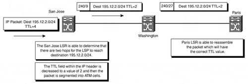
Figure 5-8 shows that when an IP packet destined for a host on network 195.12.2.0/24 arrives at the San Jose ATM edge-LSR, the IP TTL is decreased by the number of hops necessary to reach the end point of the LSP during the segmentation of the packet into cells. When the Paris ATM-LSR reassembles the original IP packet, the TTL field contained in the IP header contains the correct TTL value that reflects the number of hops the packet traversed.
The problem with this approach, however, is that anomalies are produced when using traceroute across the ATM portion of the network. Reducing the MPLS/IP TTL by 1 is sufficient to prevent forwarding loops. In the Cisco implementation of the MPLS architecture, the ATM edge-LSR decreases the TTL by 1?regardless of the number of hops?prior to the segmentation of the frame into cells. By using this method, you can rely on TTL for regions of the network that are frame-forwarded, including the edge of the ATM cloud, and you can assume that control procedures (as discussed in the previous section) prevent loops within the ATM portion of the network.


