Internet Connectivity Through Dynamic Default Routing
In many cases, VPN customers will require Internet access through a specific exit point, but they may consider that the use of static default routes is not dynamic enough. This Internet access may be provided through the service provider's exit points, or it may be provided through a customer central site. In either case, a default route pointing to the Internet exit point is sufficient. However, it is certainly desirable for this default route to be available to the VRF through a dynamic mechanism rather than through static configuration.
Dynamic Default Routing?Route Target Assignment
Central site Internet access is common with many VPN deployments. We have already seen how multiple exit points can be used through configuration of static routes into the customer VRFs. However, a dynamic method is required so that Internet access is provided only through use of a default route if the exit point is actually available.
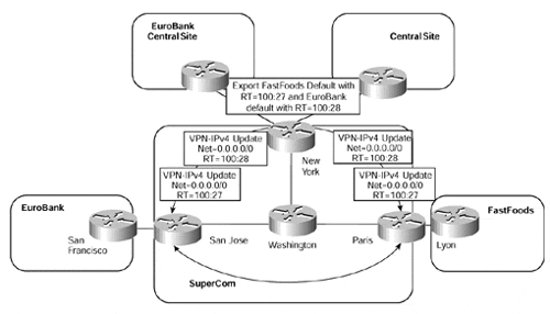
One method of achieving this aim is to use BGP extended community route target attributes that correspond to a default route. This default route will point to the relevant central site that provides the Internet access and will be contained within the VPN customers' VRF. An example of this type of connectivity can be seen in Figure 12-28.
Figure 12-28. Central Site Internet Connectivity Using Default Routing

Figure 12-28 shows that the New York PE-router exports the default route from the EuroBank VRF with a route target of 100:28, and the default route from the FastFoods VRF with a route target of 100:27. When these routes are imported into the EuroBank and FastFoods VRFs at other PE-routers, all Internet traffic will be sent toward the correct central site exit point for each of the VPNs.
If this default route is learned from across the PE-to-CE link, then no further configuration is necessary. However, if the default route must be generated from within the VRF, then use of the network 0.0.0.0 command within the BGP VRF configuration should be utilized. This can be seen in Example 12-17.
Example 12-17 Generation of Default Route from Within the VRF
Hostname San Jose

!

ip vrf EuroBank

 rd 1:27

 route-target both 100:27

!

router bgp 1

 neighbor 194.22.15.3 remote-as 1

 neighbor 194.22.15.3 update-source Loopback0

!

 address-family ipv4 vrf EuroBank

  neighbor 10.2.1.25 remote-as 2

  neighbor 10.2.1.25 activate

  network 0.0.0.0 mask 0.0.0.0

!


San Jose # show ip bgp vpnv4 vrf EuroBank tags


Network          next-hop      In tag/Out tag

Route Distinguisher: 100:27 (EuroBank)

0.0.0.0          10.2.1.25       29/notag


San Jose # show ip bgp vpnv4 vrf EuroBank 0.0.0.0


BGP routing table entry for 1:27:0.0.0.0/0, version 17

Paths: (1 available, best #1, table EuroBank)

  Advertised to non peer-group peers:

  194.22.15.3 10.2.1.25

  Local

    10.2.1.25 from 0.0.0.0 (194.22.15.2)

      Origin IGP, metric 0, localpref 100, weight 32768, valid,

      sourced, local, best

      Extended Community: RT:100:27
Association of the Global Routing Table with a VRF
Although the previous example is fine for a single customer that wants to gain access to the Internet through its own central site, it is not sufficient if multiple customers require access to the Internet through use of a dynamic default route. In this case, a route target can be associated with each Internet exit point within the service provider backbone. Each VPN customer will gain Internet access through the exit point that is associated with the route target imported into the VRF. This is similar to the example shown in Figure 12-28, except that either the default route will point to one of the service provider's Internet exit point interfaces (instead of a customer central site), or it will be treated as an aggregate route by the advertising PE-router and a lookup of the Layer 3 header will be performed.
If the advertising PE-router has only one interface toward the Internet, then the default route that it generates may point toward this interface. This interface need not be associated with a VRF. Because this default route is associated with an outgoing interface, all incoming traffic that holds the relevant VPN label that will have been assigned to the default route will be label-switched out of the interface. The implications of this are that the next router in the path must be capable of routing the packet based on the global routing table. Example 12-18 provides a configuration to allow the generation of a default route with a specific Internet exit point route target.
Example 12-18 Generation of Default Route Outside a VRF
hostname San Jose

!

ip vrf Internet_access

 rd 1:29

 route-target export 100:29

!

router bgp 1

 !

 address-family ipv4 vrf Internet_access

 redistribute static

 network 0.0.0.0 mask 0.0.0.0

!

ip route vrf Internet_access 0.0.0.0 0.0.0.0 atm2/0/0.1


San Jose # show ip bgp vpnv4 vrf Internet_access 0.0.0.0


BGP routing table entry for 1:29:0.0.0.0/0, version 24

Paths: (1 available, best #1, table Internet_access)

  Advertised to non peer-group peers:

  194.22.15.3

  Local

    0.0.0.0 from 0.0.0.0 (194.22.15.2)

      Origin IGP, metric 0, localpref 100, weight 32768, valid,

      sourced, local, best

      Extended Community: RT:100:29


San Jose # show tag forwarding vrf Internet_access


Local  Outgoing    Prefix            Bytes tag  Outgoing   next-hop

tag    tag or VC   or Tunnel Id      switched   interface

38     Untagged    0.0.0.0/0[V]      0          AT2/0/0.1  point2point
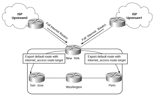
If multiple exit points exist from the same PE-router, as in Figure 12-29, then a default route pointing to an interface would not allow load balancing across multiple exit point interfaces. Traffic would be switched out of one interface only, based on the configured default route. It is certainly possible to configure multiple default routes so that load balancing on the same PE-router can be achieved; however, this can lead to sub-optimal routing if the chosen exit point is not the shortest path.
Figure 12-29. Multiple Internet Exit Points on PE-routers

Figure 12-29 shows that the New York PE-router has two interfaces that connect to the Internet. Full Internet routing is received through both interfaces, and the best routes are selected through the standard BGP decision process. To take advantage of this decision process and thus send all Internet traffic along the best path, each Internet exit point interface must be associated with the same VRF.
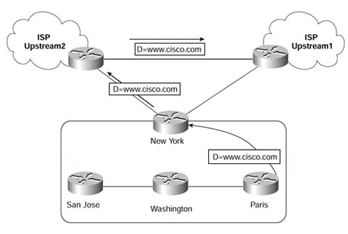
If the association of the global routing table with a VRF approach is taken, it is necessary to make sure that the full Internet routes exist within the VRF so that the destination of the packet can be resolved at the end of the label-switched path (LSP). When the routes reside within the VRF, and only a default route is required by VPN customers, then the default route within the VRF should be generated as an aggregate label so that a lookup within the VRF will be performed on all packets that use the default route. If the default is not generated as an aggregate, and if multiple exit points exist, then routing will still be successful. However, it could be suboptimal or, in extreme cases, a routing loop. This problem is illustrated in Figure 12-30.
Figure 12-30. Sub-optimal Routing with Multiple Internet Exit Points

Imagine that you configure an Internet VRF in the New York router and then insert all routes received from both upstream ISPs into that VRF. You also configure static default routes pointing toward these upstream ISPs. A default route is then propagated (with a specific route target) to all other PE-routers and is imported into all relevant VRFs on the Paris PE-router. When traffic is sent to the Paris PE-router from a VPN customer that uses one of these VRFs, this traffic is sent to the New York PE-router. The New York PE-router has two default routes: One of these points to the Upstream1 ISP, and the other points to the Upstream2 ISP. Both of these defaults are contained within the Internet access VRF, and the same label is assigned to both default routes within this VRF.
In this case, the Paris PE-router will send any packets (if a no more specific route exists within the VRF) toward the New York PE-router with two labels. One label is used for the default route, and the other label is used to get the packet to the New York router.
The first label will be popped one hop before the New York PE-router so that it will receive a packet with just the label for the default route attached. Because the same label is assigned to both of the default routes within the VRF, the New York router is capable of performing load balancing across the two upstream links. This means that it will send the packet to either the Upstream1 or Upstream2 routers as an unlabeled IP packet after removing the default route label.
If we assume that the packet is sent to the Upstream2 router, then this router will route the packet as normal, based on the information in its global routing table. However, the best path toward a particular destination might be via the Upstream1 ISP, so the packet will be sent toward the Upstream1 router, as displayed in Figure 12-30. Therefore, there is the potential for suboptimal routing.
To remedy this situation, it is possible to generate a default route that contains an aggregate label. As we have already described, an aggregate label causes a PE-router to perform a lookup within the relevant VRF. If full Internet routes are available within this VRF, then optimal routing can be achieved. In our example, the generation of an aggregate label can be achieved by assigning only one static default route on the New York PE-router. This static route can be configured to point to a next-hop address that is a loopback address on the PE-router. The loopback interface need not be part of the VRF. The static route is placed into the VRF and is treated as an aggregate label, which means that a lookup in the VRF is performed for any packet using this label.


