Hierarchical Virtual Private Networks
Some ISP customers of the MPLS/VPN backbone may want to provide MPLS/VPN services for their own customers. The implications of this are that VPN-IPv4 routes and their corresponding labels must be exchanged between ISP sites and must be imported into relevant VPN customer VRFs within the ISP site. This is essentially the same model as the carrier's carrier architecture that we have already seen, except that the ISP-customer external routes will be contained within a VRF rather than the global routing table of the ISP.
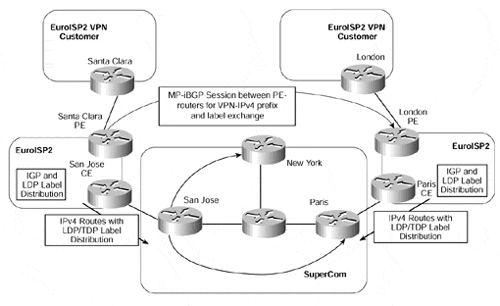
This type of connectivity is known as hierarchical VPN, sometimes referred to as recursive VPN. Its deployment is similar to our previous examples, except that Multiprotocol iBGP is introduced for the distribution of prefix and label information between ISP sites. A sample topology using this connectivity option can be seen in Figure 14-11.
Figure 14-11. Hierarchical VPN Connectivity

Within each ISP site in Figure 14-11, the PE-routers hold VRF routing information for any VPN customers that are attached to the POP MPLS/VPN backbone. This is no different than the standard MPLS/VPN architecture, so VPN-IPv4 prefixes are assigned to customer VPN routes and are distributed between ISP sites using MP-iBGP with BGP extended community attributes (Route Target and Site of Origin).
Because each POP site may hold several PE-routers, a full mesh of MP-iBGP is necessary among all PE-routers within the ISP MPLS/VPN topology. However, again, route reflectors can be deployed to cut down on the number of required peering sessions. In the example shown in Figure 14-11, it would be possible, for example, for the EuroISP2 London and Santa Clara PE-routers to be route reflectors for their own EuroISP2 site. You could even deploy totally separate devices and make each PE-router a route reflector client so that MP-iBGP updates can be successfully reflected to all PE-routers that need the VPN information contained within the updates.
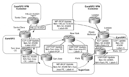
Figure 14-12 provides an example of the relevant label assignment for the 146.22.15.0/24 prefix, which is learned from a VPN customer of the EuroISP2 Santa Clara site.
Figure 14-12. Hierarchical VPN Connectivity (Label Assignment)

The figure shows again that labels are advertised both within the MPLS/VPN backbone and within each ISP site, for each of the ISP-customer internal routes. ISP-customer external routes are distributed between sites as VPN-IPv4 routes (instead of IPv4 routes as with the carrier's carrier solution). This means that the iBGP session between sites becomes an MP-iBGP session so that VPN-IPv4 routes, and their associated labels, can be successfully advertised.
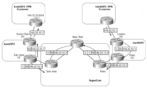
The actual traffic flow for a packet destined for a host on the 146.22.15.0/24 subnet and arriving at the EuroISP2 London PE-router is illustrated in Figure 14-13.
Figure 14-13. Hierarchical VPN Connectivity (Traffic Flow)


