Controlling the Distribution of Label Mappings
In Chapter 2, "Frame-mode MPLS Operation," you saw that an Interior Gateway Protocol (IGP) is used within an MPLS network to discover IP prefix information, which is associated with a particular forwarding equivalent class (FEC). After the LSR discovers this information, a label might be assigned to the FEC and advertised to all upstream LDP/TDP neighbors, depending on whether downstream or downstream-on-demand label distribution mode is in operation.
The decision of whether to assign a label to an FEC is based on which control mode is in operation. There are two such modes: ordered and independent. . Chapter 2 shows that when you deploy ordered LSP control, which is the default mode for an ATM-LSR, an LSR binds only a label to a particular FEC if it is the egress LSR for that FEC, or if it has received a label binding already from the next-hop LSR for that FEC. When you use independent mode, which is the default when using Frame-mode MPLS, an LSR binds a label to an FEC independently of the label it has to receive from the next-hop LSR. This is similar to link-state IP routing, where each router builds its routing table independently.
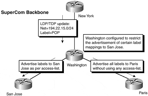
Because of the way labels bind to FECs, it is not possible within the MPLS architecture to restrict which FECs have labels associated to them and which do not. Therefore, if label switching to a particular FEC is not desirable (which may be the case during a migration to the MPLS architecture), you need a mechanism that can filter the advertisement of label mappings so that an upstream LSR neighbor does not receive label mapping for a particular FEC. Without this label mapping information, the upstream LSR cannot label switch to the destination FEC and, therefore, must route packets based on the IP routing table information. Figure 5-1 illustrates this technique.
Figure 5-1. Control of Label Distribution Between Adjacent LSRs

You can see from Figure 5-1 that the Washington LSR is configured to restrict the advertisement of label mappings to the San Jose LSR but not the Paris LSR. This configuration is achieved through the use of the tag-switching advertise-tags global command. Table 5-1 shows the syntax of this command.
|
Command |
Purpose |
|---|---|
|
tag-switching advertise-tag [for access-list-for-definition-prefixes] [to access-list-for-TDP/LDP-peers] |
Filter label mappings to TDP/LDP peers based on destination prefixes specified in a standard access-list |
Table 5-1 shows that two arguments exist for the tag-switching advertise-tags command. The for argument uses an access-list that specifies the destination IP prefixes that either must be permitted or denied. The to argument uses an access-list to specify to which TDP/LDP neighbors the previous for argument should be applied. The access list specified in the to argument should match the TDP/LDP identifier of the neighbor. This identifier can be displayed with the show tag-switching tdp neighbor command, as shown in Example 5-1, where the neighbor TDP identifier is highlighted in the printout.
Note
It is important to ensure that stable addresses are used for the TDP/LDP identifier. Therefore, make sure a loopback address is available for use as the identifier. If multiple loopbacks are used, use the tag-switching tdp router-id command to specify which loopback address to use as the TDP/LDP identifier.
You can see the necessary configuration for the Washington LSR in Example 5-2.
Example 5-1 tag-switching tdp neighbor Command
washington# show tag-switching tdp neighbor


Peer TDP Ident: 194.22.15.2:0; Local TDP Ident 194.22.15.3:0

        TCP connection: 194.22.15.2.12226 ? 194.22.15.3.711

        State: Oper; PIEs sent/rcvd: 122/117; ; Downstream

        Up time: 01:37:24

        TDP discovery sources:

          ATM0/0/0.1

        Addresses bound to peer TDP Ident:

          10.1.1.13       194.22.15.2
Example 5-2 tag-switching advertise-tags Configuration Example
hostname Washington

!

tag-switching advertise-tags for 1 to 2

tag-switching tdp router-id Loopback0

!

interface Loopback0

 ip address 194.22.15.3 255.255.255.255

!

interface ATM0/0/0

 no ip address

 no atm ilmi-keepalive

!

interface ATM0/0/0.1 point-to-point

 description ** interface to San Jose **

 ip address 10.1.1.14 255.255.255.252

 atm pvc 1 20 20 aal5snap

 tag-switching ip

!

interface Ethernet0/1/0

 description ** interface to Paris **

 ip address 10.2.1.22 255.255.255.252

 tag-switching ip

!

interface POS2/0/0

 description ** interface to New York **

 ip address 10.1.1.21 255.255.255.252

 tag-switching ip

!

access-list 1 permit 194.22.15.0 0.0.0.255

access-list 1 deny   any

access-list 2 deny 195.22.15.1
The tag-switching advertise-tags command can be used only when running Frame-mode MPLS. This means that if the link between two LSRs is via an LC-ATM interface, then the filtering of label mappings is not possible.
Note
It is worth noting that you can use an ATM interface within the configuration of the Washington router and to connect to the San Jose router. However, this interface is not an LC-ATM interface; therefore, a traditional ATM Forum PVC is configured across the interface between the two routers. In this case, the router uses Frame-mode for that particular interface, although it is an ATM interface, and therefore the tag-switching advertise-tags command works.
The reason for this restriction is that when running across an LC-ATM interface, the router uses ordered LSP control mode and downstream-on-demand label distribution. When using this mode of operation, interface resources are used as labels. In the case of ATM, these are VPI/VCI pairs and are known as label virtual circuits (LVCs). Chapter 3, "Cell-mode MPLS Operation," discusses LVCs. The consequence of this is that if the advertisement of label mappings were filtered, then all traffic across the link would be sent across the control virtual circuit (VPI 0 VCI 32). This is because the destination prefix would be shown as untagged within the LFIB and any traffic toward that prefix would be routed. Because the next-hop for the destination prefix of the packet would point toward the downstream neighbor that is reachable via the control virtual circuit, all traffic would follow this path. This is not a desirable function because this virtual circuit is used for control messaging and routing protocol traffic and is not intended to carry IP traffic.


