Multiprotocol Label Switching (MPLS) Introduction
Multiprotocol Label Switching (MPLS) is an emerging technology that aims to address many of the existing issues associated with packet forwarding in today's Internetworking environment. Members of the IETF community worked extensively to bring a set of standards to market and to evolve the ideas of several vendors and individuals in the area of label switching. The IETF document draft-ietf-mpls-framework contains the framework of this initiative and describes the primary goal as follows:
The primary goal of the MPLS working group is to standardize a base technology that integrates the label swapping forwarding paradigm with network layer routing. This base technology (label swapping) is expected to improve the price/performance of network layer routing, improve the scalability of the network layer, and provide greater flexibility in the delivery of (new) routing services (by allowing new routing services to be added without a change to the forwarding paradigm).
Note
You can download IETF working documents from the IETF home page (http://www.ietf.org). For MPLS working documents, start at the MPLS home page (http://www.ietf.org/html.charters/mpls-charter.html).
The MPLS architecture describes the mechanisms to perform label switching, which combines the benefits of packet forwarding based on Layer 2 switching with the benefits of Layer 3 routing. Similar to Layer 2 networks (for example, Frame Relay or ATM), MPLS assigns labels to packets for transport across packet- or cell-based networks. The forwarding mechanism throughout the network is label swapping, in which units of data (for example, a packet or a cell) carry a short, fixed-length label that tells switching nodes along the packets path how to process and forward the data.
The significant difference between MPLS and traditional WAN technologies is the way labels are assigned and the capability to carry a stack of labels attached to a packet. The concept of a label stack enables new applications, such as Traffic Engineering, Virtual Private Networks, fast rerouting around link and node failures, and so on.
Packet forwarding in MPLS is in stark contrast to today's connectionless network environment, where each packet is analyzed on a hop-by-hop basis, its layer 3 header is checked, and an independent forwarding decision is made based on the information extracted from a network layer routing algorithm.
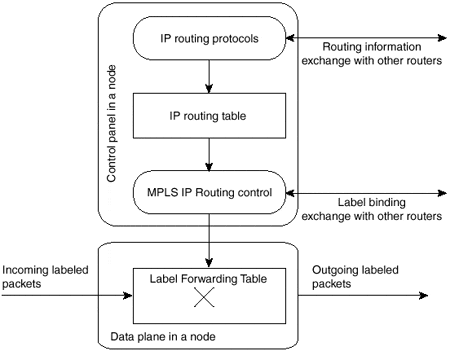
The architecture is split into two separate components: the forwarding component (also called the data plane) and the control component (also called the control plane). The forwarding component uses a label-forwarding database maintained by a label switch to perform the forwarding of data packets based on labels carried by packets. The control component is responsible for creating and maintaining label-forwarding information (referred to as bindings) among a group of interconnected label switches. Figure 1-3 shows the basic architecture of an MPLS node performing IP routing.
Figure 1-3. Basic Architecture of an MPLS Node Performing IP Routing

Every MPLS node must run one or more IP routing protocols (or rely on static routing) to exchange IP routing information with other MPLS nodes in the network. In this sense, every MPLS node (including ATM switches) is an IP router on the control plane.
Similar to traditional routers, the IP routing protocols populate the IP routing table. In traditional IP routers, the IP routing table is used to build the IP forwarding cache (fast switching cache in Cisco IOS) or the IP forwarding table (Forwarding Information Base [FIB] in Cisco IOS) used by Cisco Express Forwarding (CEF).
In an MPLS node, the IP routing table is used to determine the label binding exchange, where adjacent MPLS nodes exchange labels for individual subnets that are contained within the IP routing table. The label binding exchange for unicast destination-based IP routing is performed using the Cisco proprietary Tag Distribution Protocol (TDP) or the IETF-specified Label Distribution Protocol (LDP).
The MPLS IP Routing Control process uses labels exchanged with adjacent MPLS nodes to build the Label Forwarding Table, which is the forwarding plane database that is used to forward labeled packets through the MPLS network.
MPLS Architecture?The Building Blocks
As with any new technology, several new terms are introduced to describe the devices that make up the architecture. These new terms describe the functionality of each device and their roles within the MPLS domain structure.
The first device to be introduced is the Label Switch Router (LSR). Any router or switch that implements label distribution procedures and can forward packets based on labels falls under this category. The basic function of label distribution procedures is to allow an LSR to distribute its label bindings to other LSRs within the MPLS network. (Chapter 2, "Frame-mode MPLS Operation," discusses label distribution procedures in detail.)
Several different types of LSR exist that are differentiated by what functionality they provide within the network infrastructure. These different types of LSR are described within the architecture as Edge-LSR, ATM-LSR, and ATM edge-LSR. The distinction between various LSR types is purely architectural?a single box can serve several of the roles.
An Edge-LSR is a router that performs either label imposition (sometimes also referred to as push action) or label disposition (also called pop action) at the edge of the MPLS network. Label imposition is the act of prepending a label, or a stack of labels, to a packet in the ingress point (in respect of the traffic flow from source to destination) of the MPLS domain. Label disposition is the reverse of this and is the act of removing the last label from a packet at the egress point before it is forwarded to a neighbor that is outside the MPLS domain.
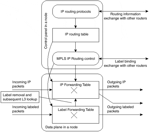
Any LSR that has any non-MPLS neighbors is considered an Edge-LSR. However, if that LSR has any interfaces that connect through MPLS to an ATM-LSR, then it also is considered to be an ATM edge-LSR. Edge-LSRs use a traditional IP forwarding table, augmented with labeling information, to label IP packets or to remove labels from labeled packets before sending them to non-MPLS nodes. Figure 1-4 shows the architecture of an Edge-LSR.
Figure 1-4. Architecture of an Edge-LSR

An Edge-LSR extends the MPLS node architecture from Figure 1-3 with additional components in the data plane. The standard IP forwarding table is built from the IP routing table and is extended with labeling information. Incoming IP packets can be forwarded as pure IP packets to non-MPLS nodes or can be labeled and sent out as labeled packets to other MPLS nodes. The incoming labeled packets can be forwarded as labeled packets to other MPLS nodes. For labeled packets destined for non-MPLS nodes, the label is removed and a Layer 3 lookup (IP forwarding) is performed to find the non-MPLS destination.
An ATM-LSR is an ATM switch that can act as an LSR. The Cisco Systems, Inc. LS1010 and BPX family of switches are examples of this type of LSR. As you see in the following chapters, the ATM-LSR performs IP routing and label assignment in the control plane and forwards the data packets using traditional ATM cell switching mechanisms on the data plane. In other words, the ATM switching matrix of an ATM switch is used as a Label Forwarding Table of an MPLS node. Traditional ATM switches, therefore, can be redeployed as ATM-LSRs through a software upgrade of their control component.
Table 1-1 summarizes the functions performed by different LSR types. Please note that any individual device in the network can perform more than one function (for example, it can be Edge-LSR and ATM edge-LSR at the same time).
|
LSR Type |
Actions Performed by This LSR Type |
|---|---|
|
LSR |
Forwards labeled packets. |
|
Edge-LSR |
Can receive an IP packet, perform Layer 3 lookups, and impose a label stack before forwardding the packet into the LSR domain. |
|
Can receive a labeled packet, remove labels, perform Layer 3 lookups, and forward the IP packet toward its next-hop. |
|
|
ATM-LSR |
Runs MPLS protocols in the control plane to set up ATM virtual circuits. Forwards labeled packets as ATM cells. |
|
ATM edge-LSR |
Can receive a labeled or unlabeled packet, segment it into ATM cells, and forward the cells toward the next-hop ATM-LSR. |
|
Can receive ATM cells from an adjacent ATM-LSR, reassemble these cells into the original packet, and then forward the packet as a labeled or unlabeled packet. |
Label Imposition at the Network Edge
Label imposition has been described already as the act of prepending a label to a packet as it enters the MPLS domain. This is an edge function, which means that packets are labeled before they are forwarded to the MPLS domain.
To perform this function, an Edge-LSR needs to understand where the packet is headed and which label, or stack of labels, it should assign to the packet. In conventional layer 3 IP forwarding, each hop in the network performs a lookup in the IP forwarding table for the IP destination address contained in the layer 3 header of the packet. It selects a next hop IP address for the packet at each iteration of the lookup and eventually sends the packet out of an interface toward its final destination.
Note
Some forwarding mechanisms, such as CEF, allow the router to associate each destination prefix known in the routing table to the adjacent next-hop of the destination prefix, thus solving the recursive lookup problem. The whole recursion is resolved while the router populates the cache or the forwarding table and not when it has to forward packets.
Choosing the next hop for the IP packet is a combination of two functions. The first function partitions the entire set of possible packets into a set of IP destination prefixes. The second function maps each IP destination prefix to an IP next hop address. This means that each destination in the network is reachable by one path in respect to traffic flow from one ingress device to the destination egress device (multiple paths might be available if load balancing is performed using equal-cost paths or unequal-cost paths as with some IGP protocols, such as Enhanced IGRP).
Within the MPLS architecture, the results of the first function are known as Forwarding Equivalence Classes (FECs). These can be visualized as describing a group of IP packets that are forwarded in the same manner, over the same path, with the same forwarding treatment.
Note
A Forwarding Equivalence Class might correspond to a destination IP subnet, but also might correspond to any traffic class that the Edge-LSR considers significant. For example, all interactive traffic toward a certain destination or all traffic with a certain value of IP precedence might constitute an FEC. As another example, an FEC can be a subset of the BGP table, including all destination prefixes reachable through the same exit point (egress BGP router).
With conventional IP forwarding, the previously described packet processing is performed at each hop in the network. However, when MPLS is introduced, a particular packet is assigned to a particular FEC just once, and this is at the edge device as the packet enters the network. The FEC to which the packet is assigned is then encoded as a short fixed-length identifier, known as a label.
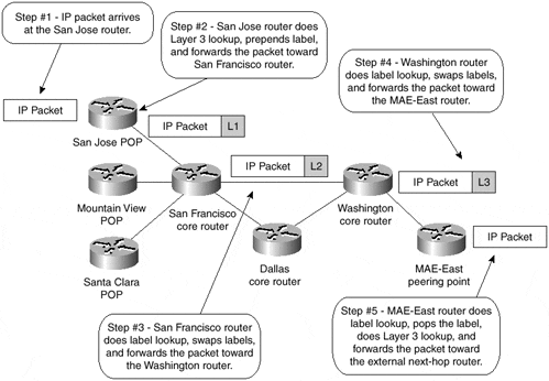
When a packet is forwarded to its next hop, the label is prepended already to the IP packet so that the next device in the path of the packet can forward it based on the encoded label rather than through the analysis of the Layer 3 header information. Figure 1-5 illustrates the whole process of label imposition and forwarding.
Note
The actual packet forwarding between the Washington and MAE-East routers might be slightly different from the one shown in Figure 1-5 due to a mechanism called penultimate hop popping (PHP). Penultimate hop popping arguably might improve the switching performance, but does not impact the logic of label switching. Chapter 2 covers this mechanism and its implications.
Figure 1-5. MPLS Label Imposition and Forwarding

MPLS Packet Forwarding and Label Switched Paths
Each packet enters an MPLS network at an ingress LSR and exits the MPLS network at an egress LSR. This mechanism creates what is known as an Label Switched Path (LSP), which essentially describes the set of LSRs through which a labeled packet must traverse to reach the egress LSR for a particular FEC. This LSP is unidirectional, which means that a different LSP is used for return traffic from a particular FEC.
The creation of the LSP is a connection-oriented scheme because the path is set up prior to any traffic flow. However, this connection setup is based on topology information rather than a requirement for traffic flow. This means that the path is created regardless of whether any traffic actually is required to flow along the path to a particular set of FECs.
As the packet traverses the MPLS network, each LSR swaps the incoming label with an outgoing label, much like the mechanism used today within ATM where the VPI/VCI is swapped to a different VPI/VCI pair when exiting the ATM switch. This continues until the last LSR, known as the egress LSR, is reached.
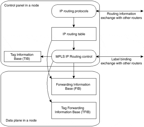
Each LSR keeps two tables, which hold information that is relevant to the MPLS forwarding component. The first, known in Cisco IOS as the Tag Information Base (TIB) or Label Information Base (LIB) in standard MPLS terms, holds all labels assigned by this LSR and the mappings of these labels to labels received from any neighbors. These label mappings are distributed through the use of label-distribution protocols, which Chapter 2 discusses in more detail.
Just as multiple neighbors can send labels for the same IP prefix but might not be the actual IP next hop currently in use in the routing table for the destination, not all the labels within the TIB/LIB need to be used for packet forwarding. The second table, known in Cisco IOS as the Tag Forwarding Information Base (TFIB) or Label Forwarding Information Base (LFIB) in MPLS terms, is used during the actual forwarding of packets and holds only labels that are in use currently by the forwarding component of MPLS.
Note
Label Forwarding Information Base is the MPLS equivalent of the switching matrix of an ATM switch.
Using Cisco IOS terms and Cisco Express Forwarding (CEF) terminology, the Edge-LSR architecture in Figure 1-4 can be redrawn as shown in Figure 1-6 (Edge-LSR was chosen because its function is a superset of non?Edge-LSR).
Figure 1-6. Edge-LSR Architecture Using Cisco IOS Terms


