Case Study: Basic MPLS/VPN Intranet Service
One of the simplest VPN topologies you can provision using the MPLS/VPN architecture is an Intranet between multiple sites that belong to the same organization. This topology is the basic VPN network structure that provides any-to-any connectivity between sites using the enhanced peer-to-peer model discussed in Chapter 7, "Virtual Private Network (VPN) Implementation Options." Using the same mechanisms you use to build the Intranet topology, you can add more advanced services and connectivity requirements.
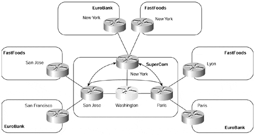
Figure 9-1 shows an example of this type of topology, which is used as a case study throughout this chapter.
Figure 9-1. Basic MPLS/VPN Intranet Topology Structure

In Figure 9-1, you can see that the SuperCom MPLS/VPN backbone has two VPN customers: EuroBank and FastFoods. The EuroBank organization has sites in San Francisco, New York, and Paris. The FastFoods organization has sites in San Jose, New York, and Lyon. Both customer sites have the any-to-any, non-redundant, Intranet VPN service from the SuperCom MPLS/VPN backbone, with only one CE-to-PE connection.
The SuperCom service provider learns routes from both VPN customers through a combination of RIP Version 2 and static routing. The EuroBank San Francisco site and the FastFoods San Jose site both use RIP Version 2 to communicate with the MPLS/VPN backbone, whereas the FastFoods Lyon/New York and EuroBank Paris/New York sites use static routing.
Table 9-1 shows the relevant address space for both VPN customers, and the loopback addresses used by the SuperCom backbone for BGP sessions.
|
Company |
Site |
Subnet |
|---|---|---|
|
FastFoods |
San Jose |
195.12.2.0/24 |
|
New York |
10.2.2.0/24 |
|
|
Lyon |
10.2.1.0/24 |
|
|
EuroBank |
San Francisco |
10.2.1.0/24 |
|
New York |
10.1.2.0/24 |
|
|
Paris |
196.7.25.0/24 |
|
|
SuperCom |
Paris (Loopback 0) |
194.22.15.1/32 |
|
San Jose (Loopback 0) |
194.22.15.2/32 |
|
|
New York (Loopback 0) |
194.22.15.3/32 |
To provision this VPN service across the MPLS/VPN backbone, follow these steps:
Define and configure the VRFs.
Define and configure the route distinguishers.
Define and configure the import and export policies.
Configure the PE-to-CE links.
Associate the CE-interfaces to the previously defined VRFs.
Configure the Multiprotocol BGP.
Throughout the rest of this chapter, you examine in more detail each of these mechanisms and you can follow the configuration of the SuperCom San Jose PE-router (refer to Figure 9-1) to learn how to provision the basic MPLS/VPN architecture.


