MPLS/VPN Migration?Staging and Execution
When all the policies and design specifics have been decided, then the migration to an MPLS/VPN solution can take place. Much of the preliminary migration work, such as the migration of customer routes into BGP, and the deployment of MPLS within the internal network infrastructure, will have already been completed at this stage. However, as with all deployments, it is good practice to review the currently deployed solution to make sure that all prerequisite items have been completed. In the case of a migration to MPLS/VPN, these prerequisites will include all the things discussed in Chapter 6.
Within our case study example, the SampleNet central site will require some attention because it will be necessary to migrate the VPN sites in a staged manner rather than as a complete switchover to the new solution.
Migration of the SampleNet Central Site
The migration of the SampleNet central site location is tricky because it requires that connectivity between VPN sites be maintained throughout the migration. To achieve this goal, it will be necessary to make some changes to the current central site configuration to allow the GRE tunnel endpoints to be reachable and to ensure that the central site is capable of learning other VPN site prefixes that will be advertised across the TransitNet backbone using MP-iBGP. Figure 15-3 shows the current central site connectivity into the TransitNet backbone.
Figure 15-3. SampleNet Central Site Connectivity
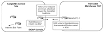
This figure shows that the TransitNet Manch-PE-1 PE-router connects via an ATM PVC to the SampleNet central site, and uses BGP to advertise the GRE tunnel endpoints from other VPN sites toward the central site and to receive updates that contain the prefix information contained within the central site. At the central site, redistribution occurs among the routing protocol running at the central site, EIGRP, and BGP so that any prefixes that must be available to other members of the VPN are reachable.
As previously mentioned, during the migration, it will be necessary for the TransitNet service provider to maintain VPN connectivity for SampleNet sites via the existing GRE tunneling method as sites are moved onto the new MPLS/VPN infrastructure. This means that a certain amount of suboptimal routing will occur. (This is discussed in more detail in the following sections, although this suboptimal routing is already apparent in the existing GRE tunneled solution.) This also requires the addition of a further ATM PVC between the Manch-PE-1 PE-router and the central SampleNet site.
This new PVC will be used to carry traffic from SampleNet VPN sites that have been migrated over to the new MPLS/VPN solution. The use of this link is necessary to allow for connectivity between GRE tunneled sites and MPLS/VPN sites during the migration, and this link will ultimately be used as a replacement to the existing PVC when a full migration has been completed. This solution can be seen in Figure 15-4, which provides the topology and traffic flow during the migration stage.
Figure 15-4. SampleNet Central Site Migration Scenario
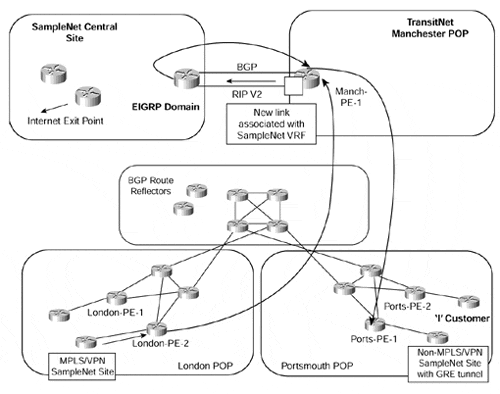
Figure 15-4 shows that one of the links (ATM PVC) to the central SampleNet site will carry BGP routes, and the other will run RIP Version 2. At this stage of the deployment, all routes learned across the BGP sessions will be standard BGP-4 routes, not VPN-IPv4 routes, so everything will flow across this link and will be advertised toward the central site. During the migration, the only routes that will be advertised across the link will be from non-MPLS/VPN SampleNet customers that are still using the GRE tunneling configuration. It is necessary for these routes to be advertised to the main site so that two-way connectivity is established. The only routes that will be learned from the main site across this link are the GRE tunnel endpoint addresses.
The second link will be configured to run RIP Version 2, and this will carry any routes that have been placed into the VRF associated with the link. This VRF will belong to the Snet_Internet VPN and will learn only the default route from the central site that will have been redistributed from EIGRP (central site routing protocol) into RIP Version 2. Until customer routes are moved into the Snet_Customer VPN, the default route will be the only route contained within the Snet_Internet VRF. No routes will be advertised toward the central SampleNet site across this link until the Snet_Internet VRF is populated with routes that match the Snet_Customer route target value of 1234:16.
The traffic flow from a non-MPLS SampleNet site to an MPLS/VPN SampleNet site will traverse the main site and be sub-optimal. This is because the non-MPLS customer traffic will be resolved by using the global routing table where the MPLS/VPN SampleNet site routes will not reside. This means that the traffic will enter the GRE tunnel and exit at the main SampleNet site. This site will have learned the MPLS/VPN site routes via the redistribution of RIP Version 2 into EIGRP and therefore will send the traffic back to the TransitNet backbone for delivery to the MPLS/VPN site. On the return path, because the MPLS/VPN sites will have learned the default route from the central site, any routes that are not part of the VRF (such as non-MPLS sites) will be reachable through use of the default route.
When all SampleNet sites have been moved over to the MPLS/VPN solution, then the original ATM PVC to the central SampleNet site may be removed. The routing will become optimal across the TransitNet backbone and will be based upon the information contained within the Snet_Customer VRF.
The steps necessary to migrate the main SampleNet site are as follows:
Initialization of the second ATM PVC to the SampleNet central site? The second link will be provided by way of an ATM PVC that will be in a shutdown state. This PVC should be activated at this stage.
Configuration of RIP Version 2? RIP Version 2 should be configured across the new link to carry the MPLS/VPN routes to the SampleNet central site.
Redistribution between routing protocols configuration? The necessary redistribution configuration should be applied, which includes the redistribution of the EIGRP default route into RIP Version 2, and RIP Version 2 routes into EIGRP, at the SampleNet central site router.
Configuration of MPLS/VPN? When all of the link and routing protocol configuration has been completed, the PE-router that attaches to the SampleNet central site can be configured for MPLS/VPN. At this stage, no traffic will traverse the second ATM PVC because no SampleNet VPN sites will have been moved into the VPN. Several configuration steps are necessary:
Configure the Snet_Internet VRF, including the route distinguisher and route target import/export policies, as per Example 15-1.
Associate the new link with the Snet_Internet VRF using the command ip vrf forwarding Snet_Internet within the interface configuration of the link to the central SampleNet site.
Configure the RIP Version 2 address family to advertise the VRF routes toward the SampleNet central site. The VPN routes learned from other PE-routers via MP-iBGP are redistributed into RIP Version 2 and are advertised to the CE-router using the configuration in Figure 15-2.
Example 15-1 Snet_Internet VRF Configuration Example
ip vrf Snet_Internet

 rd 1234:101

 route-target export 1234:17

 route-target import 1234:17

 route-target import 1234:16
Example 15-2 RIP Version 2 Configuration for the Snet_Internet VRF
router rip

 version 2

 !

 address-family ipv4 vrf Snet_Internet

 version 2

 redistribute bgp 1234 metric 1

 no auto-summary

 exit-address-family


