Frame-mode MPLS Data Plane Operation
Chapter 1 briefly described the propagation of an IP packet across an MPLS backbone. There are three major steps in this process:
The Ingress Edge-LSR receives an IP packet, classifies the packet into a forward equivalence class (FEC), and labels the packet with the outgoing label stack corresponding to the FEC. For unicast destination-based IP routing, the FEC corresponds to a destination subnet and the packet classification is a traditional Layer 3 lookup in the forwarding table.
Core LSRs receive this labeled packet and use label forwarding tables to exchange the inbound label in the incoming packet with the outbound label corresponding to the same FEC (IP subnet, in this case).
When the Egress Edge-LSR for this particular FEC receives the labeled packet, it removes the label and performs a traditional Layer 3 lookup on the resulting IP packet.
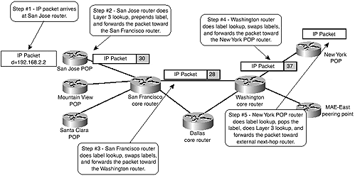
Figure 2-3 shows these steps being performed in the SuperNet network for a packet traversing the network from the San Jose POP toward a customer attached to the New York POP.
Figure 2-3. Packet Forwarding Between San Jose POP and New York Customer

The San Jose POP router receives an IP packet with the destination address of 192.168.2.2 and performs a traditional Layer 3 lookup through the IP forwarding table (also called Forwarding Information Base [FIB]).
Note
Because Cisco Express Forwarding (CEF) is the only Layer 3 switching mechanism that uses the FIB table, CEF must be enabled in all the routers running MPLS and all the ingress interfaces receiving unlabeled IP packets that are propagated as labeled packets across an MPLS backbone must support CEF switching.
The core routers do not perform CEF switching?they just switch labeled packets?but they still must have CEF enabled globally for label allocation purposes.
The entry in the FIB (shown in Example 2-1) indicates that the San Jose POP router should forward the IP packet it just received as a labeled packet. Thus, the San Jose router imposes the label "30" into the packet before it's forwarded to the San Francisco router, which brings up the first question: Where is the label imposed and how does the San Francisco router know that the packet it received is a labeled packet and not a pure IP packet?
Example 2-1 CEF Entry in the San Jose POP Router
SanJose#show ip cef 192.168.2.0

192.168.2.0/24, version 11, cached adjacency to Serial1/0/1

0 packets, 0 bytes

  tag information set

    local tag: 29

    fast tag rewrite with Se1/0/1, point2point, tags imposed: {30}

  via 172.16.1.4, Serial1/0/1, 0 dependencies

    next hop 172.16.1.4, Serial1/0/1

    valid cached adjacency

    tag rewrite with Se1/0/1, point2point, tags imposed: {30}
MPLS Label Stack Header
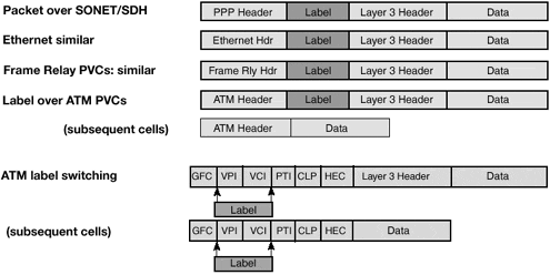
For various reasons, switching performance being one, the MPLS label must be inserted in front of the labeled data in a frame-mode implementation of the MPLS architecture. The MPLS label thus is inserted between the Layer 2 header and the Layer 3 contents of the Layer 2 frame, as displayed in Figure 2-4.
Figure 2-4. Position of the MPLS Label in a Layer 2 Frame

Due to the way an MPLS label is inserted between the Layer-3 packet and the Layer-2 header, the MPLS label header also is called the shim header. The MPLS label header (detailed in Figure 2-5) contains the MPLS label (20 bits), the class-of-service information (three bits, also called experimental bits, in the IETF MPLS documentation), and the eight-bit Time-to-Live (TTL) field (which has the identical functions in loop detection as the IP TTL field) and one bit called the Bottom-of-Stack bit.
Note
Please see Chapter 5, "Advanced MPLS Topics," for a detailed discussion on loop detection and prevention in an MPLS (both frame-mode and cell-mode) environment.
Figure 2-5. MPLS Label Stack Header

The Bottom of Stack bit implements an MPLS label stack, which Chapter 1 defined as a combination of two or more label headers attached to a single packet. Simple unicast IP routing does not use the label stack, but other MPLS applications, including MPLS-based Virtual Private Networks or MPLS Traffic Engineering, rely heavily on it.
With the MPLS label stack header being inserted between the Layer 2 header and the Layer 3 payload, the sending router must have some means to indicate to the receiving router that the packet being transmitted is not a pure IP datagram but a labeled packet (an MPLS datagram). To facilitate this, new protocol types were defined above Layer 2 as follows:
In LAN environments, labeled packets carrying unicast and multicast Layer 3 packets use ethertype values 8847 hex and 8848 hex. These ethertype values can be used directly on Ethernet media (including Fast Ethernet and Gigabit Ethernet) as well as part of the SNAP header on other LAN media (including Token Ring and FDDI).
On point-to-point links using PPP encapsulation, a new Network Control Protocol (NCP) called MPLS Control Protocol (MPLSCP) was introduced. MPLS packets are marked with PPP Protocol field value 8281 hex.
MPLS packets transmitted across a Frame Relay DLCI between a pair of routers are marked with Frame Relay SNAP Network Layer Protocol ID (NLPID), followed by a SNAP header with type ethertype value 8847 hex.
MPLS packets transmitted between a pair of routers over an ATM Forum virtual circuit are encapsulated with a SNAP header that uses ethertype values equal to those used in the LAN environment.
Note
For more details on MPLS transport across non-MPLS WAN media, see Chapter 4, "Running Frame-mode MPLS Across Switched WAN Media."
Figure 2-6 sho ws the summary of all the MPLS encapsulation techniques.
Figure 2-6. Summary of MPLS Encapsulation Techniques

The San Jose router in the example shown in Figure 2-3 inserts the MPLS label in front of the IP packet just received, encapsulates the labeled packet in a PPP frame with a PPP Protocol field value of 8281 hex, and forwards the Layer 2 frame toward the San Francisco router.
Label Switching in Frame-mode MPLS
After receiving the Layer 2 PPP frame from the San Jose router, the San Francisco router immediately identifies the received packet as a labeled packet based on its PPP Protocol field value and performs a label lookup in its Label Forwarding Information Base (LFIB).
Note
LFIB also is called Tag Forwarding Information Base (TFIB) in older Cisco documentation.
The LFIB entry corresponding to inbound label 30 (and displayed in Example 2-2) directs the San Francisco router to replace the label 30 with an outbound label 28 and to propagate the packet toward the Washington router.
Example 2-2 LFIB Entry for Label 30 in the San Francisco Router
SanFrancisco#show tag forwarding-table tags 30 detail

Local  Outgoing    Prefix            Bytes tag  Outgoing   Next Hop

tag    tag or VC   or Tunnel Id      switched   interface

30     28          192.168.2.0/24    0          Se0/0/1    172.16.3.1

        MAC/Encaps=14/18, MTU=1504, Tag Stack{28}

        00107BB59E2000107BEC6B008847 0001C000

    Per-packet load-sharing
The labeled packet is propagated in a similar fashion across the SuperNet backbone until it reaches the New York POP, where the LFIB entry tells the New York router to pop the label and forward the unlabeled packet (see Example 2-3).
Example 2-3 LFIB Entry in the New York Router
NewYork#show tag forwarding-table tags 37 detail

Local  Outgoing    Prefix            Bytes tag  Outgoing   Next Hop

tag    tag or VC   or Tunnel Id      switched   interface

37     untagged       192.168.2.0/24 0          Se2/1/3    192.168.2.1

        MAC/Encaps=0/0, MTU=1504, Tag Stack{}

    Per-packet load-sharing
A Cisco router running Cisco IOS software and operating as an MPLS LSR in Frame-mode MPLS can perform a number of actions on a labeled packet:
Pop tag? Removes the top label in the MPLS label stack and propagates the remaining payload as either a labeled packet (if the bottom-of-stack bit is zero) or as an unlabeled IP packet (the Tag Stack field in the LFIB is empty).
Swap tag? Replaces the top label in the MPLS label stack with another value (the Tag Stack field in the LFIB is one label long)
Push tag? Replaces the top label in the MPLS label stack with a set of labels (the Tag Stack field in the LFIB contains several labels).
Aggregate? Removes the top label in the MPLS label stack and does a Layer 3 lookup on the underlying IP packet. The removed label is the bottom label in the MPLS label stack; otherwise, the datagram is discarded.
Untag? Removes the top label in the MPLS label stack and forwards the underlying IP packet to the specified IP next-hop. The removed label is the bottom label in the MPLS label stack; otherwise, the datagram is discarded.
MPLS Label Switching with Label Stack
The label switching operation is performed in the same way regardless of whether the labeled packet contains only one label or a label stack several labels deep. In both cases, the LSR switching the packet acts only on the top label in the stack, ignoring the other labels. This function enables a variety of MPLS applications where the edge routers can agree on packet classification rules and associated labels without knowledge of the core routers.
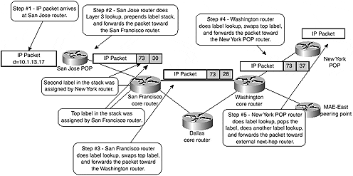
For example, assume that the San Jose router and the New York router in the SuperNet network support MPLS-based Virtual Private Networks and that they have agreed that network 10.1.0.0/16, which is reachable through the New York router, is assigned a label value of 73. The core routers in the SuperNet network (San Francisco and Washington) are not aware of this.
To send a packet to a destination host in network 10.1.0.0/16, the San Jose router builds a label stack. The bottom label in the stack is the label agreed upon with the New York router, and the top label in the stack is the label assigned to the IP address of the New York router by the San Francisco router. When the network propagates the packet (as displayed in Figure 2-7), the top label is switched exactly like in the example where a pure IP packet was propagated across the backbone and the second label in the stack reaches the New York router intact.
Figure 2-7. Label Switching with the MPLS Label Stack


