Multiprotocol BGP Deployment in an MPLS/VPN Backbone
As already discussed in Chapter 8, "MPLS/VPN Architecture Overview," and Chapter 9, "MPLS/VPN Architecture Operation," the introduction of a VPN service based on the MPLS architecture requires MP-iBGP sessions between all PE-routers that hold routing information for the same VPN or set of VPNs. Because these sessions are iBGP sessions, and the number of PE-routers could potentially be high, this presents a scaling issue due to the sheer number of MP-iBGP peering sessions required between PE-routers. This is not an uncommon situation when BGP is deployed because of the nature of iBGP, which requires that each iBGP speaker run a direct BGP session with every other iBGP speaker that originates routes into BGP.
We have already discussed certain methods that are available to the designer to aid in the scaling of these peering sessions. We recommend in this environment that BGP route reflectors be deployed so that the number of required internal BGP peering sessions is considerably reduced. A further possibility is the introduction of BGP confederations. Both of these methods were discussed in detail in Chapter 12.
Even when these methods are deployed, BGP may still have issues with scaling. When routing information changes occur, a router must scan the whole BGP table for each of its neighbors. This process causes a BGP update to be built on each iteration of the scanning process. If multiple neighbors exist, then multiple BGP updates are built. This has a detrimental effect on the router's resources (CPU load and memory). Therefore, the use of BGP peer groups is further recommended if the router uses the same outbound policies toward each BGP neighbor. The introduction of peer groups will allow the BGP router to create in memory just one single pdate for all members of the peer group.
When changes occur within the topology, the BGP table is scanned only once. A single outbound BGP update is built for one of the neighbors that is a member of the peer group (also called the peer group leader) and is sent to every member of the peer group.
Note
The router automatically chooses the peer group leader. You cannot influence the selection of the peer group leader , but you can monitor which neighbor becomes the peer group leader by using the show ip bgp neighbor command.
Because the same update is sent to all members of a peer group, you must configure the same outbound policy for every neighbor that is a member of that peer group.
Note
Cisco IOS also enforces this requirement by preventing you from configuring any per-neighbor BGP parameter that might affect outbound updates on individual BGP neighbors that are also members of a peer group.
VPN Routes and Next-hop Forwarding
As has already been highlighted, a PE-router may learn customer VPN routes through various different sources. These routes may be learned through a VPN instance of an internal routing protocol such as RIP Version 2 or OSPF, through static routing, or through an external routing protocol such as BGP. Regardless of how these customer VPN routes are learned, all of them must be advertised to other PE-routers; this is achieved through utilizing MP-iBGP in the way that we described in the Multiprotocol BGP Usage and Deployment section of Chapter 9. Therefore, when the MPLS/VPN architecture is introduced into the network, all customer VPN routes will be carried by BGP across the backbone and will not be injected into the service provider's IGP.
When the routes are learned through any other method other than BGP, these routes must be injected into MP-iBGP through redistribution. In all cases, routes learned through VPN routing instances must be readvertised in BGP with the PE as the next-hop. This is because the label advertised with the route is assigned by the originating PE-router. This is not the case, by default, when learning routes through non-VPN eBGP.
In a standard BGP implementation, the default behavior of an eBGP speaker that has sessions to external neighbors is to advertise, unchanged, any routes that it learns from these neighbors to all internal neighbors. Therefore, the next-hop attribute of the route contains the IP address of the external neighbor that announced the route. Additional processing takes place when the same route is propagated through several BGP sessions between routers connected to the same multiaccess media. In that case, the next-hop is set to the interface IP address of the first router that announced the route across a BGP session over that multiaccess media.
The effect of this is that all the links that are used to carry the non-VPN eBGP sessions need to be known within the IGP of the service provider. This behavior should not really be necessary in many cases, and these links need to be known only within the service provider IGP if they must be reachable for some reason (for instance, for network management of the links). Therefore, a mechanism is needed that will allow a non-VPN BGP-speaking router to advertise external routes without having to inject the external link IP addresses into the internal IGP. This can be achieved through use of the next-hop-self command within the BGP configuration; an example of this can be seen in Example 13-3.
Note
As will be seen later, this command is not necessary for VPN because, by default the PE-router will announce the route with itself as the next-hop.
Example 13-3 Use of next-hop-self for BGP Route Advertisement
router BGP <AS #>

!

 neighbor x.x.x.x remote-as <remote-as-#>

 neighbor x.x.x.x next-hop-self
Note
In a non-VPN environment, the IP subnets of links connecting the customers to the service provider backbone are usually not inserted into BGP by the service provider. Therefore, if the service provider wants to perform any network management of the customer-to-provider links , such as do SNMP requests on the customer router or ping IP addresses on the customer-to-provider links, they still must carry those subnets within the IGP. On the other hand, if the service provider only monitors link availability by reading SNMP tables on the PE-router, the IP subnet connecting the customer to the provider does not have to be reachable by other parts of the provider backbone.
Note also that just monitoring the SNMP tables on the PE-router does not guarantee that you'll be able to discover connectivity problems?the physical link might appear operational but does not pass any customer traffic. Also, if the link belongs to a VPN customer and is associated with a VRF, the link address will not be reachable within the service provider's IGP address space because it will have been removed from the global routing table.
We have already seen that when MPLS/VPN is introduced into the network, PE-routers will propagate VPN routes through the use of MP-iBGP. We have also seen that the PE-routers need to propagate labels that point toward the egress PE-router that announces these VPN routes.
Because each PE-router that announces VPN routes is the endpoint of any label-switched path (LSP) toward the VPN destination, the architecture requires that the PE-router announce itself as the BGP next-hop for the route so that label forwarding can occur and so that the PE-router can switch the packet based on the content of the second level label that corresponds to the relevant VRF and outbound interface for the route.
As previously stated, to guarantee successful forwarding of labeled VPN packets across the provider backbone, each PE-router will announce itself as the next-hop for any routes that it sends across MP-iBGP sessions by default; there is no need to specify this within the configuration of the PE-router. This next-hop address should be one of the loopback addresses of the advertising PE-router because this type of interface is always available.
Note
The PE-router will use the address specified within the update-source parameter of the neighbor command. This should be one of the loopback addresses.
The proper handling of the BGP next-hop is a necessary condition only for proper forwarding of VPN data. The ingress PE-routers also need a label toward the BGP next-hop (the loopback address of the egress router) in their forwarding table so that they can set the top MPLS label of the VPN packets to the label that has been assigned for the egress PE-router's loopback address. This means that all PE loopback addresses must be carried within the service provider's IGP, but they need not be host routes (although the use of host routes facilitates better usage of service provider address space?see the PE-router Loopback Address Configuration section, later in this chapter).
Note
Also refer to Chapter 8 and Chapter 9 for a further detailed discussion of VPN packet forwarding across the service provider backbone.
All internal links within the backbone must be enabled for MPLS switching so that a TDP/ LDP relationship can be formed and so that the distribution of labels between adjacent LSRs can be achieved. If a router-only backbone is used, a label will be assigned to every internal route by the LSR, and this is determined by what is contained with the routing table. In normal Frame-mode MPLS operation, these labels will be advertised to upstream neighbors using downstream label distribution procedures. However, a label is required only for these internal links if packets will be sent directly to them. To prevent the advertisement of all these labels, the filtering techniques already discussed in Chapter 5, "Advanced MPLS Topics," should be deployed.
Note
Note that such filters will prevent only the advertisement of these labels, not their origination and subsequent insertion into the router's LFIB.
PE-router Loopback Address Configuration
Whenever a loopback address is configured and assigned an IP address, it is desirable for this IP address to be seen as a /32 host route within the IGP. This saves on address space and requires the use of only one address from a block of addresses for this particular interface. This is not strictly necessary or specified within the MPLS/VPN architecture, but it is certainly recommended.
In the case where the IGP is Open Shortest Path First (OSPF), then the loopback address should always be configured with a /32 mask. This is because OSPF will always set the address of a loopback interface to a host route, regardless of the configured mask for that interface. This OSPF behavior can be overridden by forcing the OSPF process to see the loopback address as a point-to-point link by using the ip ospf network point-to-point command within the loopback configuration. However, it is more advisable to use a /32 host route for the loopback address to conserve address space.
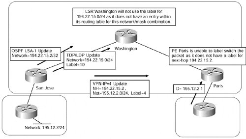
The implications of this behavior are pretty severe within an MPLS environment and will cause a loss of connectivity if not strictly adhered to. This is because if the loopback address is configured with a mask that is not /32?for instance, /24?there will be a difference between the OSPF route within its database and the LDP/TDP label. The LDP/TDP binding will refer to a route with a mask of /24 because the routing table of the LSR knows the loopback address as a connected /24 route.
In Figure 13-4, when LSR San Jose exchanges label bindings for all its routes with other LSRs, which will include a binding for its loopback interface, it will include a label binding for the loopback /24 route, not the /32 route that is contained within the OSPF database. All other LSRs will not use any label bindings that they receive if there is no corresponding route within their local routing table.
Figure 13-4. PE Loopback Address Assignment

This means that when LSR Washington in Figure 13-4 receives the /24 label binding for 194.22.15.0/24 from LSR San Jose (it will not have received an IGP update for this route?it will have received a /32 route via OSPF because this is what is contained within the OSPF database of LSR San Jose), this /24 label binding will never be considered for use. Thus, connectivity to any destinations that use an address within the /24 subnet as a next-hop will be lost.
Summarization of PE Loopback Addresses
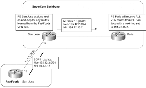
We have already seen that whenever a PE-router advertises a customer VPN route or any other external route to another PE-router, it does so with itself as the BGP next-hop. This next-hop address will be the address used for the MP-iBGP peering to other PE-routers, which will typically be one of its loopback interfaces. This can be seen in Figure 13-5, with sample configuration and router output shown in Examples 13-4 and 13-5.
Figure 13-5. MP-iBGP Update Next-hop Assignment

Figure 13-5 shows that PE-router San Jose receives an update from a VPN neighbor that is running BGP-4 across the PE-to-CE link for prefix 195.12.2/24. PE-router San Jose then advertises this route to PE-router Paris, but with the next-hop set to 194.22.15.2, which is the loopback address used by the San Jose PE-router for the MP-iBGP session to PE-router Paris.
Example 13-4 MP-iBGP Update Configuration
hostname San Jose

!

ip vrf FastFoods

 rd 1:26

 route-target both 100:26

!

interface Loopback0

 ip address 194.23.16.1 255.255.255.255

!

interface Loopback1

 ip address 194.22.15.2 255.255.255.255

!

interface serial0

 ip vrf forwarding FastFoods

 ip address 10.1.1.14 255.255.255.252

!

router bgp 1

 no bgp default ipv4-unicast

 neighbor 194.22.15.1 remote-as 1

 neighbor 194.22.15.1 update-source loopback1

!

 address-family ipv4 vrf FastFoods

 redistribute connected

 neighbor 10.1.1.13 remote-as 2

 neighbor 10.1.1.13 activate

 no auto-summary

 no synchronization

 exit-address-family

 !

address-family vpnv4

 neighbor 194.22.15.1 activate

 neighbor 194.22.15.1 send-community extended

 exit-address-family

!


hostname Paris

!

interface Loopback0

 ip address 194.22.15.1 255.255.255.255

!

router bgp 1

 no bgp default ipv4-unicast

 neighbor 194.22.15.2 remote-as 1

 neighbor 194.22.15.2 update-source Loopback0

!

 address-family vpnv4

 neighbor 194.22.15.2 activate

 neighbor 194.22.15.2 send-community extended

 exit-address-family

!
Example 13-5 MP-iBGP Update show ip route vrf Output
San Jose# show ip route vrf FastFoods 195.12.2.0

Routing entry for 195.12.2.0/24

  Known via "bgp 1", distance 20, metric 0

  Tag 2, type external

  Last update from 10.1.1.13 on serial0, 01:01:58 ago

  Routing Descriptor Blocks:

  * 10.1.1.13, from 10.1.1.13, 01:01:58 ago, via serial0

      Route metric is 0, traffic share count is 1

      AS Hops 1


Paris# show ip bgp vpnv4 vrf FastFoods 195.12.2.0

BGP routing table entry for 1:26:195.12.2.0/24, version 15

Paths: (1 available, best #1, table FastFoods)

Flag: 0x208

  Not advertised to any peer

  2

    194.22.15.2 (metric 40000) from 194.22.15.2 (194.22.15.2)

      Origin IGP, metric 0, localpref 100, valid, internal, best

      Extended Community: RT:100:26
Note
Notice that PE-router San Jose has a loopback0 interface that has an IP address of 194.23.16.1; this address is not used as the BGP next-hop. However, if the peering session between PE-router San Jose and PE-router Paris is changed so that the configuration of PE-router Paris reflects 194.23.16.1 as the MP-iBGP session endpoint, all routes will be advertised with a next-hop of 194.23.16.1 from PE-router San Jose.
You might think that with multiple PE-routers spread across the network, it may be desirable to summarize the loopback address ranges to help reduce the size of the routing table. However, when MPLS is used within the core of the network, the addresses that are used for the loopback interfaces of PE-routers must not be summarized anywhere within the network because this will cause a loss of connectivity across the backbone. This is regardless of whether the advertised routes are for VPN customers or non-VPN customers.
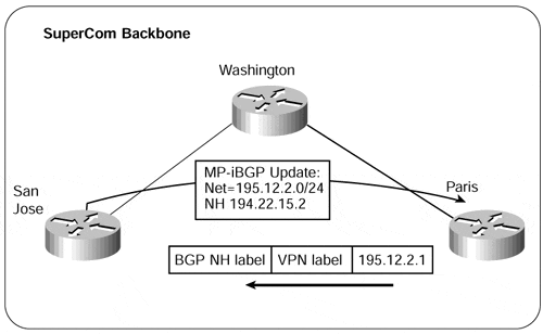
To understand the need to avoid summarization, we must consider how internal routers will forward packets based on their MPLS information. We have already seen that regardless of whether the route is for a non-VPN or a VPN customer, a next-hop is used that corresponds to the advertising PE-router. This means that whenever a packet is forwarded to an external destination, a label is appended to the packet that corresponds to the BGP next-hop of the route, this being the egress PE-router. This label will be the first label in the MPLS label stack; as mentioned previously, it will be the label that corresponds to the egress PE-router's loopback interface address. An illustr ation of this is shown in Figure 13-6.
If the BGP next-hop were summarized by any P-routers within the core, they would become the endpoint of the label-switched path (LSP) for the route. In other words, the top label, pointing toward the egress PE-router, would be removed, and the P-router would be faced with a packet that it might not be capable of recognizing. The implications of this are slightly different for non-VPN and VPN routes.
In the case of non-VPN routes, the user data is sent across the provider backbone with only one MPLS label, pointing toward the egress PE-router. Whenever the P-router becomes a summarization point, it advertises the implicit-null label to upstream neighbors for each summarized route, requesting them to remove the top label. When the top label is removed, the P-router is faced with a pure IP packet. This means that the P-router would need to use information from its own routing table to forward the packet. Because no BGP information is advertised to P-rout ers, connectivity is lost and all packets for destinations covered by the summary would be dropped.
Figure 13-6. MPLS Two-Level Label Stack

Note
Theoretically, it is still possible to summarize loopback addresses in non-VPN networks if the router doing the summarization also carries full BGP routing. However, we definitely advise against such practice.
In the case of VPN routes, if the BGP next-hop address is summarized somewhere within the backbone at a point that is between two PE-routers exchanging MP-iBGP routes, then any VPN connectivity between these two routers is lost.
After the top MPLS label is removed, the P-router is faced with a labeled packet with the second label in the original MPLS label stack as its top label. This second label, imposed on the VPN packet by the ingress PE-router, was assigned to the VPN destination by the originating egress PE-router. Because we know that the labels have only local significance, the meaning of this label is completely unknown to the P-router.
In this case, the upstream P-router looks for a label corresponding to the /32 of the BGP next-hop. Because it does not have a downstream label for this route, it treats it as untagged. When the P-router removes the top label and finds another label underneath, it discards the packet, resulting in no connectivity to the VPN destination. This behavior prevents packets from being forwarded along an incorrect LSP.
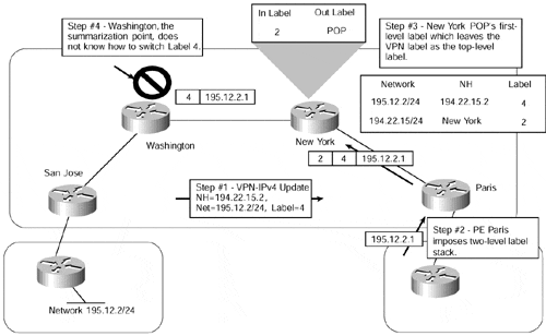
Figure 13-7 provides an example of a customer VPN route being advertised between two PE-routers, and illustrates the problem of summarizing the PE loopback addresses.
Figure 13-7. Summarization of PE Loopback Addresses

Figure 13-7 shows that PE-router San Jose advertises a VPN route for network 195.12.2/24 to PE-router Paris using its MP-iBGP session. When a packet for a host on network 195.12.2/24 arrives on PE-router Paris, it imposes a two-level stack of labels to the packet (with the top label being the label advertised by the SuperCom New York router for the next-hop, and the next label being the label advertised by the San Jose PE-router for the final VPN destination) and forwards it toward the SuperCom New York P-router.
When the New York router receives the packet, it POPs the first-level label (because it received the implicit-null label from the Washington P-router) and forwards the packet to the Washington P-router with a one-level label stack. When the Washington router receives the packet, it has a top label that corresponds to the external route as advertised by PE-router San Jose to PE-router Paris via MP-iBGP. However, the Washington router has no information available to be capable of switching the packet based on a label assigned by some other router (in this case, the San Jose PE-router); connectivity to network 195.12.2/24 is lost as the packet is dropped.
Note
It should be noted that the number of internal routes may actually increase within the core of the network because of the requirement that summarization of PE loopback addresses is prohibited. Therefore, the size of the IGP will be close to the number of PE-routers within the backbone.


