Migration of an ATM-based Backbone to Frame-mode MPLS
Our previ ous migration example assumed that the backbone of the service provider network is made up purely of routers, interconnected through point-to-point or shared media links. This is certainly the easiest topology to migrate to an MPLS solution, but what if the backbone is made up of routers, interconnected across ATM switches via PVCs? This is certainly not an uncommon type of topology, so we should consider how this type of topology could be migrated to MPLS.
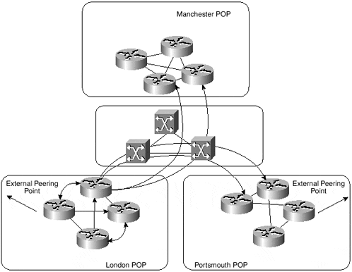
Figure 6-6 provides an example of this type of connectivity and shows that the TransitNet backbone is connected through a full mesh of ATM PVCs in the core of the network.
Figure 6-6. TransitNet Backbone Topology Using ATM Switches

This figure shows only the relevant PVCs for one of the London POP border routers, but if optimal, any-to-any connectivity is a requirement, then all other border routers within the core of the network will require a PVC with all other border routers.
The TransitNet service provider has essentially two choices with this type of connectivity. First, it could opt to migrate the ATM switches to MPLS and run IP+ATM within the backbone, creating a point-to-point type topology in which each of the border routers requires only a single connection (or multiple connections, for redundancy) into the ATM network, rather than multiple virtual circuits to other border routers. Second, the service provider could choose to deploy MPLS across the existing infrastructure and run either PVCs or permanent virtual path connections (PVPs) between ATM edge LSRs. Neither of these methods (PVCs and PVPs) are good long-term solutions, however, because they suffer from the scaling issues that we have already described, despite the use of VP tunnels that allows the ATM edge LSR to use different VCs for different FECs, rather than sending all traffic across the same PVC.
As an interim migration step, the TransitNet service provider has chosen to deploy the second option and to run MPLS across its existing PVCs. This is exactly the same type of connectivity that we examined in Chapter 4, "Running Frame-mode MPLS Across Switched WAN Media." Using this method, the service provide can enable MPLS across the whole backbone and pass IP traffic across the ATM PVCs using Frame-mode MPLS. This is no different than our previous example of the migration of a router-only backbone, and it provides a simple first-stage migration of the existing backbone to an MPLS-based solution.
As a second-stage migration, the service provider either can migrate the existing ATM infrastructure to a frame-based-only topology by simply bypassing the ATM switches and adding further frame-based LSRs, connected with point-to-point links such as POSIP, or it can migrate the existing ATM switches to provide support for MPLS and integrate the IP and ATM networks into one IP+ATM solution.
Cell-mode MPLS Migration
A migration to Cell-mode MPLS from a PV C-based topology is more involved than the migration of a router-only frame-based MPLS topology. This type of migration requires several stages to allow the existing infrastructure to be switched over to the new MPLS topology with minimal disruption to IP traffic.
In the previous section, we saw that the TransitNet backbone was converted to an MPLS solution across ATM PVCs as a temporary measure. This type of solution involves all the scaling issues that we have already discussed, so a migration to a full Cell-mode implementation is desirable.
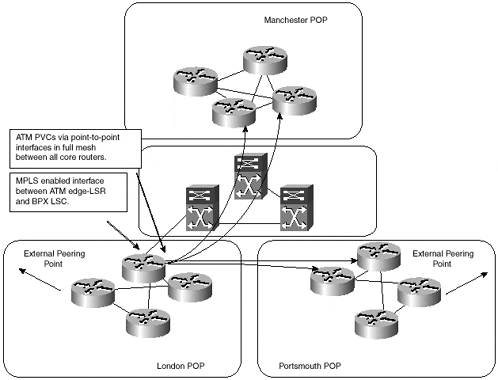
As part of the migration, all existing ATM PVCs must be maintained so that minimal disruption to traffic is achieved. In the case of the TransitNet backbone, in which the ATM topology is provided through use of Cisco BPX switches, this can be achieved by partitioning the ATM link from the ATM edge LSR to the BPX ATM-LSR so that both MPLS- and standards-based ATM PVCs can coexist across the same physical media. Figure 6-7 shows this topology.
Figure 6-7. Coexistence of MPLS and ATM PVCs

As Figure 6-7 shows, each BPX (or LS1010) switch can be converted to an MPLS-aware switch while maintaining the existing PVC-based topology. Using this method of migration, the following steps can be used to provide a staged transfer of traffic onto the new MPLS solution:
Enable the ATM switch for participation in the MPLS topology. This will include all necessary software upgrades, configuration of the switches (including the partitioning of the switch trunks), and the addition and configuration of a Label Switch Controller (LSC) in the case of BPX implementations.
When the ATM switch is ready for participation in the MPLS topology, each interface that will carry both MPLS and ATM PVC traffic must be configured. On the BPX, this includes the partitioning of the physical interface to carry MPLS traffic in one partition and AuroRoute traffic in the other partition. On the LS1010, this includes the configuration of the PVCs (which will already exist) and the enabling of MPLS on the physical interface.
The next step is the configuration of the ATM edge LSR. Because it is necessary to continue to use the existing PVCs during the migration, a further subinterface must be configured that will be used to carry MPLS traffic. The IGP cost of this interface must be higher than the interface that will carry the PVC traffic so that the PVC-based interface is always preferred over the MPLS interface. Multiple hops will exist across the MPLS path, so the cost of the MPLS interface should, in most cases, be greater by default, and no further configuration will be necessary.
When everything is configured and MPLS functionality is tested across the ATM network, the last stage of the migration is to increase the IGP cost of the PVC interface so that the MPLS-enabled interface is preferred. This will cause labels to be requested from the downstream ATM-LSR, and label switching of traffic will be achieved.
Note
For a discussion and configuration examples of running both MPLS and PVCs acro ss the same ATM interface, refer to Chapter 4.


