Carrier's Carrier Architecture?Topologies
Several possible topologies require different services from the MPLS/VPN backbone. Some ISPs will not run MPLS within their own sites, while others will run MPLS but will not provide VPN services to their customers. Some ISPs will run MPLS within their own network and will also provide a VPN service to their customers. In all cases, it is necessary to differentiate between routes that will be presented to the MPLS/VPN backbone and those that will be advertised directly between sites but not advertised to the backbone network (on a CE-router/PE-router session).
External routing information for a particular VPN customer is not necessary within the MPLS/VPN backbone because label switching is performed based on BGP next-hop addresses. This is no different than the standard MPLS/VPN model that we have seen previously. However, in the case of ISP connectivity, our goal is to exchange external routing information between ISP sites, but without having to advertise this information toward the MPLS/VPN backbone and then between PE-routers within the backbone using MP-iBGP. This means that, within an ISP's VRF, the PE-routers in an MPLS/VPN backbone should not carry routes that have been learned by that ISP from its own external BGP peerings or customers.
Only the ISP's internal routes need to be advertised by the ISP sites toward the backbone for subsequent import into relevant VRFs on the PE-router. These routes will include any internal routes that must be reachable by other members of the ISP VPN, such as BGP next-hop addresses and iBGP peering addresses, and any internal networks that provide inter-POP services, such as web hosting, server farms, and central DHCP services.
Using the route types that we defined in the previous section, we can make the distinction that ISP-customer internal routes will be advertised toward the MPLS/VPN backbone, and ISP customer external routes will not.
ISP with No MPLS Deployment Within POP Sites
Having reviewed the VPN connectivity requirements of an ISP, it is clear that we should avoid the exchange of ISP-customer external routing information between POP sites through advertisement of this routing information toward the MPLS/VPN backbone. Because of this requirement, the carrier's carrier architecture can be introduced so that the MPLS/VPN backbone is not overloaded with unnecessary external routing information.
In our first example of this architecture, the ISP may not run MPLS within its own POP sites. ISP-customer external routing information is exchanged between POP sites through the use of iBGP. This type of connectivity can be seen in Figure 14-4.
Figure 14-4. Carrier's Carrier?No MPLS Within ISP Sites
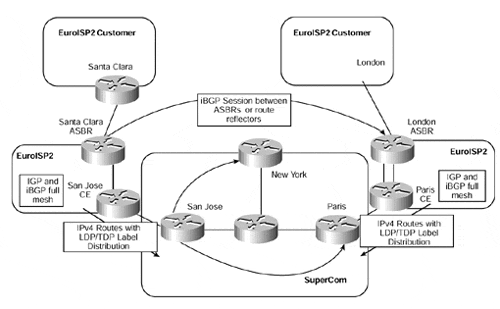
In Figure 14-4, we can see that ISP EuroISP2 wants to exchange external routing information from its Santa Clara site with other POP sites and then use the MPLS/VPN backbone to send traffic toward external destinations that are reachable through these other POP sites.
Each autonomous system boundary router (ASBR) within the ISP's sites runs an iBGP session with all other ASBRs in other POP sites so that ISP-customer external routing information can be exchanged between the sites. The BGP next-hop address for these routes must be advertised to the MPLS/VPN backbone because these addresses will subsequently be used for label switching from one site to another. This is achieved through normal routing protocol exchange across the CE-to-PE links and is no different than the mechanisms that we have already seen within the MPLS/VPN architecture.
Note
Standard iBGP rules apply where a full mesh between sites, and within sites, is required or where the use of route reflectors can be deployed to help with the scaling of the solution. If route reflectors are deployed?and this is certainly recommended?then iBGP sessions between sites can be restricted to route reflector peerings. A full mesh of iBGP sessions between route reflectors, and within each site, is still required.
All internal routes (that should be reachable by other members of the VPN) will be distributed between sites via the MPLS/VPN backbone, so each of the BGP next-hop addresses for ISP-customer external routes will be present in the VRF for the specific ISP and will be used to validate the ISP-customer external routes that are learned across the direct iBGP sessions between sites.
In our example, the San Jose PE-router will have a route within the EuroISP2 VRF that corresponds to the EuroISP2 Santa Clara ASBR router. This is because this address is used as the BGP next-hop for all routes that are advertised from the Santa Clara router to other POP sites within the EuroISP2 VPN.
The BGP next-hop addresses, and any other routes that reside within the VRF, are advertised across the MPLS/VPN backbone using MP-iBGP. They are then imported into the relevant VRFs on receiving PE-routers. In our example, the Paris PE-router will receive an MP-iBGP update that corresponds to the BGP next-hop address used by the EuroISP2 Santa Clara ASBR router for all of its ISP-customer external routes that it advertises across its iBGP session with the London ASBR. When the routes are within the VRF, they are advertised across the PE-to-CE links to all relevant VPN sites.
You might think that this is all that needs to be done to provide connectivity between ISP sites. However, as Figure 14-5 shows, packets sent from the ISP site using the information provided across their iBGP sessions are dropped at the first PE-router in the path to the destination.
Figure 14-5. ISP External Traffic?Routing Requirement at PE-router
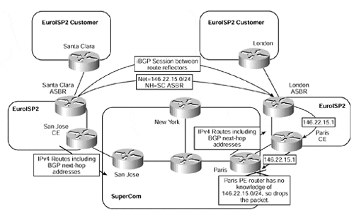
As seen in Figure 14-5, packets sent from the EuroISP2 Paris CE-router to the SuperCom Paris PE-router are dropped. This is because the PE-router has no knowledge of ISP-customer external VPN routing information (in our example, the 146.22.15.0/24 subnet) within its VRF and cannot route the packet. For this reason, each PE-to-CE link must be configured to run LDP/TDP label distribution procedures so that MPLS labels can be exchanged between the PE- and CE-routers. This is achieved through use of the mpls ip command, as shown in Example 14-1:
Example 14-1 Configuration of LDP/TDP on PE-to-CE Link
interface serial0/1

 description ** PE to CE link running LDP/TDP label distribution

 ip vrf forwarding EuroBank

 mpls ip
Once labels have been exchanged, the CE-router is capable of imposing a label for the BGP next-hop address that it has learned from the PE-router. The PE-router then can label-switch the incoming packet rather than try to route it based on information within the VRF.
Therefore, the EuroISP2 CE-routers in San Jose and Paris run LDP/TDP label distribution with the SuperCom backbone PE-routers so that they can learn labels for the BGP next-hop addresses of ISP-customer external routes from other POP sites, and also ISP-customer internal networks, across these sessions. However, because these routes were learned via BGP, the LDP/TDP label distribution is modified in this environment so that it can carry labels for BGP routes (the default behavior is to carry labels only for internal routes).
Note
When the mpls ip (or tag-switching ip) command is configured on a VRF interface, the PE-router will automatically assign a label to any routes that are learned from across the MPLS/VPN backbone. The default behavior of a VRF interface is to assign labels only to routes that are learned from any attached CE-devices rather than routes learned via the MPLS/VPN backbone. This means that when the mpls ip (or tag-switching ip) command is added to the VRF configuration, there are two label assignments: one for incoming routes from the CE-routers (standard MPLS/VPN VRF mechanism), and one for outgoing routes learned from across the MPLS/VPN backbone. This second label assignment essentially maps a new label to the label that will be received within the MP-iBGP update for the route.
These labels are assigned by the PE-router and correspond to any routes that are learned across MP-iBGP sessions and imported into the VRF. Because the ISP sites are not running MPLS, no specific label values are advertised by the CE-router toward the PE. However, every internal route within the site will have the implicit-null label assigned by the CE-router, and this will be advertised across the link to the PE-router. ISP-customer external routes that are advertised across the direct iBGP sessions between ISP sites will also have no associated labels because no LDP/TDP label distribution between the ASBRs (or route reflectors) will exist across these iBGP sessions.
Any labels used by the CE-routers must be controlled by the PE-router. This is achieved through the association of the label with a specific route contained within the VRF. In addition, the PE-router keeps track of the label values that have been assigned to each of the VRFs so that it can track which label mappings have been advertised to which CE-routers and through which interfaces, to eliminate the possibility of label spoofing.
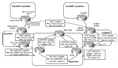
Figure 14-6 provides an illustration of the relevant label assignment for the topology already discussed in Figure 14-4. For simplicity, no IP address assignment is shown, and the router names are used to represent relevant IP addresses.
This figure shows that the EuroISP2 Santa Clara ASBR router learns prefix 146.22.15.0/24 from one of its customers. This route is advertised to internal BGP neighbors within the EuroISP2 Santa Clara site, and to other EuroISP2 sites, with a BGP next-hop address of SC-ASBR (this will be the loopback interface address used for the iBGP session). The EuroISP2 San Jose CE-router advertises the BGP next-hop address for the route?in this case, the address of the Santa Clara ASBR router (SC-ASBR)?across the link to the SuperCom San Jose PE-router using the routing protocol configured for the link.
Figure 14-6. Carrier's Carrier?No MPLS Within ISP Sites (Label Assignment)
Note
The routing protocol used across the PE-to-CE link may be any of the currently supported protocols, such as RIP Version 2, OSPF, or BGP. We will see later that when MPLS is also deployed within the VPN site, then BGP may not (currently) be used as the PE-to-CE link protocol because the CE-router cannot allocate labels to routes that are learned via BGP.
The SuperCom San Jose PE-router installs the SC-ASBR prefix into the EuroISP2 VRF and advertises it, along with an assigned label, to all other PE-routers using MP-iBGP. In Figure 14-6, the Paris PE-router receives the MP-iBGP update for the SC-ASBR prefix and imports it into the EuroISP2 VRF. Because the Paris PE-router is configured for LDP/TDP label assignment, it assigns a new label to this route. The PE-router then advertises the route across the PE-to-CE link using the standard routing protocol mechanisms, either IGP or BGP. The PE-router also advertises a label mapping using LDP/TDP with the relevant label assignment for the route.
Note
Note that if any protocol other than BGP is used across the PE-to-CE link, then redistribution from the VRF into the routing protocol running across the link is necessary, just as in the standard MPLS/VPN procedures that we have described in previous chapters.
When the Paris CE-router receives the update for the SC-ASBR prefix, it advertises it using its IGP (or iBGP, if received via a PE-to-CE eBGP session) to the London ASBR.
Note
The BGP next-hop address?SC-ASBR, in our example?can be learned across the VPN site via iBGP. However, this means that BGP synchronization must be disabled. When a BGP route is validated through other BGP routes?which is the case, in our example?you must make sure that the BGP next-hop route is not subject to synchronization.
Figure 14-7 shows the subsequent packet flow when the London ASBR receives a packet destined for a host on network 146.22.15.0/24.
Figure 14-7. Carrier's Carrier?No MPLS Within ISP Sites (Traffic Flow)
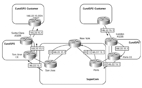
If we follow the packet flow shown in Figure 14-7, we can see that the London ASBR receives a packet destined for a host on network 146.22.15.0/24. The London ASBR looks up the 146.22.15.0/24 prefix within its forwarding table and finds a BGP route with a next-hop pointing to the Santa Clara ASBR router. This next-hop address has been learned via the EuroISP2 IGP (or possibly iBGP, if synchronization has been disabled), as advertised by the Paris CE-router. The London ASBR thus routes the packet toward the Paris CE-router.
When the Paris CE-router receives the packet, it also looks up the destination of 146.22.15.0/24 within its forwarding table and finds that the next-hop for this route is reachable via the SuperCom Paris PE-router. It also finds that a label of 33 has been assigned to this next-hop address. This is the same principle as with the basic MPLS architecture, where a label is not assigned to the BGP route; instead, we use the label that has been assigned to the next-hop of that route. The packet thus is sent to the Paris PE-router with a label of 33, which corresponds to the BGP next-hop address of the EuroISP2 Santa Clara ASBR.
When the SuperCom Paris PE-router receives the labeled packet (with label value 33), it knows that the label corresponds to the VPN route SC-ASBR as learned from its MP-iBGP session with the San Jose PE-router. This means that it swaps the label value of 33 to a label stack that will be used to reach the originating PE-router (the San Jose router, in this example). The Paris PE-router then label-switches the packet to the San Jose PE-router using the standard MPLS/VPN mechanisms that we have already seen.
The San Jose PE-router uses the VPN label to switch the packet to the EuroISP2 San Jose CE-router. Because MPLS has not been deployed within the site, no outgoing labels exist within the PE-router for the VPN prefix, so the packet is sent as an unlabeled packet. The EuroISP2 San Jose CE-router is then capable of routing the packet using its forwarding table.
ISP with MPLS Deployed Within POP Sites
Although our previous example provides a scalable solution to allow the ISP to connect its POP sites across an MPLS/VPN backbone, it still requires that traditional Layer 3 routing occur within each site and that ISP-customer external routing information be carried by all transit routers within each site. For these reasons (although, of course, these are not the only ones), an ISP customer of the MPLS/VPN backbone may choose to deploy MPLS locally within its own site and label-switch traffic end to end, from ingress ASBR to egress ASBR in another POP site.
In this environment, iBGP sessions are still required between site ASBR routers, just as in our previous example, so that ISP-customer external routing information can be learned from other sites. A full mesh of iBGP between ASBRs (or route reflectors) is also still necessary, although a full mesh of iBGP sessions is no longer required within each site. This is because label switching will be performed across the site, so internal transit routers that do not have direct customer connectivity do not need to carry external routing information. This is the same situation as described in Chapter 1, "Multiprotocol Label Switching (MPLS) Architecture Overview," where internal routers within an MPLS domain do not need to hold BGP routing information because they will forward packets based on their label values, not their Layer 3 address.
As in the previous connectivity example, only the BGP next-hop addresses and ISP-customer internal routes are required to be propagated through use of MP-iBGP across the MPLS/VPN backbone and via the site IGP so that label forwarding will be successful across the backbone and within the VPN site. This means that iBGP sessions are required only between site ASBRs and any edge routers that will receive incoming customer traffic and that, therefore, need to perform label imposition on the incoming packets.
Each CE-router within a POP site is required to inject all routes that it learns from across the PE-to-CE link, just as in the basic MPLS/VPN model, into its local IGP process. This is necessary so that labels can be assigned end to end and so that next-hop reachability of all ISP-customer external routes can be assured.
As can be seen, this type of connectivity is exactly the same mechanism as used in our previous example, with the exception that MPLS is used locally within the ISP POP sites. MPLS label switching is performed within the site, but with only one label in the label stack, pointing to the egress LSR (the BGP next-hop address of the route), which will be the ingress ASBR in the originating POP site for the FEC. An example of this type of connectivity can be seen in Figure 14-8.
Figure 14-8. Local MPLS Deployment?No Label Distribution Between Sites
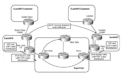
Figure 14-8 shows that each EuroISP2 site runs MPLS with LDP/TDP label distribution. When a packet enters one of the VPN sites, the ingress router performs a Layer 3 lookup within the global IP routing table to determine how to route the packet (standard packet classification). When this classification is done, a label is applied to the packet and is used to forward the packet toward the BGP next-hop of the route.
Note
In the initial release of the carrier's carrier architecture, it is a requirement that BGP not be run between CE- and PE-routers if MPLS is deployed within the ISP site. This is because the CE-router cannot allocate labels to any BGP routes that it learns from the PE-router. Static RIP Version 2 or OSPF (and in the future, possibly IS-IS and EIGRP) must be used so that the routes learned from the PE are seen as internal routes by the CE, which then allocates labels accordingly.
The label assignment used for this type of connectivity is shown in Figure 14-9. This figure provides an example of a route advertised from the Santa Clara ASBR router to the London ASBR router and shows the relevant label assignments.
Figure 14-9. Local MPLS Deployment?No Label Distribution Between Sites (Label Assignment)
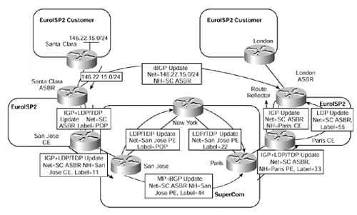
In Figure 14-9, labels are advertised both within the MPLS/VPN backbone, as with our previous example, and within each ISP site. After all the labels have been distributed through LDP/TDP, label switching can occur, both in the MPLS/VPN backbone and within each ISP site. However, no label distribution occurs across the intersite iBGP sessions, so the egress LSR?in our example, the Santa Clara ASBR?must perform an IP lookup for each packet to determine how it should be forwarded.
Using this example, Figure 14-10 shows the traffic flow and subsequent label assignment for a packet sent toward the 146.22.15.0/24 subnet from a customer attached to the EuroISP2 London site.
Figure 14-10. Local MPLS Deployment?No Label Distribution Between Sites (Traffic Flow)
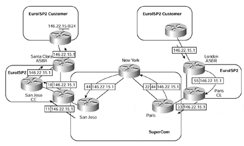
Before forwarding, the EuroISP2 London ASBR router assigns a label to any packets that are received from locally attached customers. In our example, a label value of 55 is prepended to the packet and is label-switched to the Paris CE-router across the EuroISP2 site. The Paris CE-router label switches the packet toward the Paris router, swapping the label value of 55 with a value of 33. When the SuperCom Paris PE-router receives the labeled packet, it swaps the label value of 33 for a label stack that corresponds to the VPN route and egress PE-router (the San Jose PE, in our example), and then label-switches the packet across the MPLS/VPN backbone. When the San Jose PE-router receives the packet, it uses the VPN label to forward the packet, with a label value of 11, to the EuroISP2 San Jose CE-router.
When the EuroISP2 San Jose CE-router receives the labeled packet, it label-switches it across the POP site to the Santa Clara ASBR router, which uses its global routing table to forward the packet toward the 146.22.15.0/24 subnet.


