MPLS/VPN Deployment on LAN Interfaces
Most media types provide the capability to partition the physical interface into one or multiple (sub)interfaces. Because each logical interface can belong to any VRF, this capability provides the functionality to apply multiple VRFs to the same physical interface so that multiple VPNs can share the same interface. Our discussion in Chapter 12 on Internet access for MPLS/VPN clients provides an illustration of one such topology in which this type of functionality might be required.
This capability to partition the physical interface is not available when using LAN interfaces that do not support virtual LANs (for example, standard Ethernet interfaces or Token Ring)?it is not possible to configure (sub)interfaces on these types of media. It is also not possible to associate a VRF to a secondary IP address because each VRF must be assigned to an interface, whether physical or logical, and not an IP address.
Note
Each interface can belong to only one VRF to allow the router to uniquely identify the forwarding table used for packets received through the interface in question. Two or more VRFs on the same interface would lead to ambiguities in many scenarios.
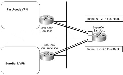
The implications of this are that standard 10-Mbps Ethernet does not provide the capability to have some hosts on one VPN and others on a totally separate VPN. In certain topologies, such as multiple customers on the same LAN segment, and for particular services, such as shared servers, this might be a very desirable function. One possible solution to this problem is to run multiple tunnels from the PE-router to each customer CE-router across the Ethernet. This option can be seen in Figure 13-8, which shows that each tunnel interface can be associated with a particular VRF to thus provide the required functionality.
Figure 13-8. Tunnel Interfaces Between PE and CE Across LAN Media

Note
The tunnel setup shown in Figure 13-8 reduces the security and isolation between the VPNs usually provided by the MPLS/VPN architecture. Every CE-router can capture packets exchanged between the PE-router and any other CE-router, resulting in loss of confidentiality. The intruder using one CE-router can also inject tunneled IP-over-IP packets with the source address of another CE-router, effectively inserting data into another VPN.
A further option is available when the interface to the shared media supports virtual local- area networks (VLANs)?for example, Fast Ethernet interfaces that are capable of supporting ISL. These VLANs can be mapped to different VPNs by associating the VLAN (sub)interface to a particular VRF.
Note
There are two conditions for successful deployment of this scenario: The interface must support VLANs, and the router must use the CEF switching path for a particular VLAN technology.
For example, Cisco IOS 12.0(7)T supports CEF switching only for ISL-based VLANs, not for 802.1q-based VLANs, so you cannot run MPLS/VPN across 802.1q-based VLANs in that particular level of IOS.
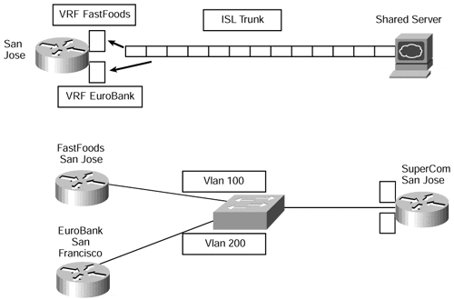
In this type of environment, Catalyst VLAN switches are connected to routers forwarding traffic from a number of ISL VLANs. The performance of this solution can be further improved with the VIP distributed ISL capability in the Cisco 7500 series router, where each VIP card can route ISL-encapsulated VLAN IP traffic. This functionality can be seen in Figure 13-9, which shows two scenarios. The first scenario shows a PE-router that is connected to a shared server that services multiple VPN clients. Each (sub)interface is used for a specific VPN access into the shared server.
Note
This type of configuration would require that the shared server be capable of servicing multiple application instances simultaneously, as well as handling VPNs that use the same address space. Although this is technically possible, research into specific server functionality is outside the scope of this publication.
The second scenario shows CE-routers connected to a PE-router through a VLAN-capable switch; each CE-router belongs to a separate VPN and is referenced through a unique (sub)interface by the PE-router.
Figure 13-9. ISL Support for PE-routers

A partial configuration for PE-router San Jose in the second scenario of Figure 13-9 can be seen in Example 13-6. This example shows that the PE-router configuration of the Fast Ethernet interface is split into two (sub)interfaces, and these are configured to belong to particular VLANs and VRFs.
Example 13-6 Fast Ethernet (Sub)interfaces and ISL Support
interface FastEthernet2/1.1

 encapsulation isl 100

 ip vrf forwarding FastFoods

!

interface FastEthernet2/1.2

 encapsulation isl 200

 ip vrf forwarding EuroBank


