IGP to BGP Migration of Customer Routes
Whenever a service provider allows access into its network infrastructure, whether for VPN service or for some other type of service such as Internet connectivity, a fundamental requirement exists to pass traffic across the network between customer access points. This requirement presents a problem for the service provider because each of the external destinations that is advertised toward, and therefore reachable by, the service provider and its customers must be known by all transit routers that will carry customer traffic across the backbone. The reason for this is that as a packet traverses the service provider network, each router in the packet's path must analyze the Layer 3 header of the packet and route it based on its destination IP address. Because the destination of the packet is for an external network, if external routing information were not held by the service provider's transit routers, then the packet would be dropped?the destination would not exist within the forwarding table of internal routers.
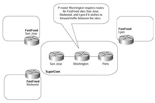
Figure 13-1 provides an example of why P-routers within the SuperCom core backbone require access to external routing information:
Figure 13-1. Full Routing Requirement for P-routers

Figure 13-1 shows that if FastFood sites San Jose, Redwood, and Lyon want to communicate across the SuperCom backbone network, then P-router Washington needs to know each of their address ranges so that it can forward traffic.
In a typical service provider environment, a couple of choices exist to allow customer routes to be carried across the core network. These two choices are either to carry the customer routes within the service provider's own Interior Gateway Protocol (IGP), or to carry the customer routes using an exterior routing protocol, most commonly BGP. In either case, internal transit routers within the core of the network (the P-routers, in MPLS/VPN terminology) must hold this routing information.
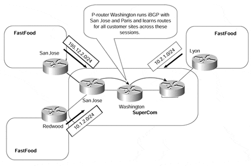
Figure 13-2 shows a typical environment. In this case, the service provider has elected to carry its customer's routes within BGP. As you can see, each of the internal routers that provide transit across the backbone (San Jose, Washington, and Paris within the SuperCom backbone) needs to hold external routing information so that it can analyze the Layer 3 header of any incoming packets and route the traffic based on its destination IP address. This information is provided through use of a full mesh of iBGP sessions between the SuperCom backbone routers.
Figure 13-2. External Routing Requirement Within the Core

Note
Traditional BGP setup would require a full mesh of iBGP sessions among all routers (edge or core) that originate routes into BGP. If any of the core routers do not originate routes into BGP (which will be a high percentage, in most backbone networks), then they do not need to be fully meshed. However, they still need an iBGP session with all edge routers?this is clearly a nonscalable environment in large network topologies.
Scalability mechanisms, such as route reflectors or BGP confederations, which we discussed in Chapter 12, "Advanced MPLS/VPN Topics," relax the full-mesh requirement and make iBGP networks scalable. These BGP concepts are covered in more details in the Cisco Press publication Internet Routing Architectures, Second Edition, by Bassam Halabi.
In most cases, the service provider elects to carry customer routes within BGP so that any instability within its customer networks does not affect the service provider's core IGP and so that the size of the internal routing protocol structure can be kept to a minimum. However, if the number of customer routes is small, some service provider's will elect to carry the routes within the IGP.
Note
In most large service provider backbones, the number of customer routes quickly grows beyond the scaling capabilities of any IGP, whether EIGRP, OSPF, or IS-IS. The service providers who initially decide to carry customer routes within their IGP sooner or later will face a challenging migration process: They will be forced to migrate their customer routes to BGP because of scalability and stability issues.
In most backbone environments, reachability to these external customer destinations is necessary only so that end-to-end customer connectivity can be achieved. The backbone devices themselves, described previously as P-devices, do not actually source traffic toward these destinations, so they need to know about them only for the reasons that we have already described.
One of the goals that the MPLS architecture hopes to achieve is to increase the scalability of IP-based networks. This scalability enhancement is provided in several ways, some of which we discussed in the previous chapter. One such way is for internal routers (P-routers) to forward packets to external destinations without having to carry external routing information. We have already seen within this chapter that this is certainly a desirable mechanism and that this eliminates some of the existing scalability issues that a service provider faces. It also fits in nicely with our desire to carry customer routes within BGP, but with the added advantage that this BGP information is not required within the core of the network.
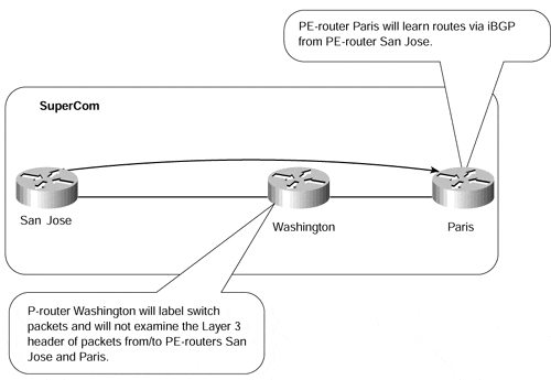
MPLS is capable of achieving this functionality because, within the backbone network, labels are not generated for BGP routes, but are generated for the next-hop addresses of these routes. This means that packets destined for external BGP destinations are sent across the service provider backbone with labels that correspond to the egress router that advertised the external route. Because these packets are labeled inside the backbone, each core router does not need to analyze the IP header and can label-switch the packet toward the egress PE-router. Because the router does not need to look at the IP header, it therefore does not need to learn BGP routing information to forward the packet. The consequence of this is that BGP information is required only at the edge of the network so that customer routes can be distributed across the backbone and between PE-routers. An example of this can be seen in Figure 13-3.
Figure 13-3. BGP Routing Across an MPLS Core Network

Figure 13-3 shows an example in which BGP information is not required within the core of the network. When MPLS is enabled within the SuperCom backbone, P-router Washington can switch packets based on their labels, so it does not need to hold BGP information. Examples 13-1 and 13-2 show the routing table and LFIB for PE-router Paris in Figure 13-3.
Example 13-1 Routing Table Output for BGP and IGP Routes
Paris# show ip route

     194.22.15.0/32 is subnetted, 1 subnets

C       194.22.15.1 is directly connected, Loopback0

     194.22.15.0/32 is subnetted, 1 subnets

i L1    194.22.15.2 [115/51765] via 10.2.1.26, Ethernet6/0

     10.0.0.0/8 is variably subnetted, 3 subnets, 2 masks

i L1    10.1.1.12/30 [115/51765] via 10.2.1.26, Ethernet6/0

B       10.1.2.0/24 [200/0] via 194.22.15.2, 00:19:01

C       10.2.1.24/30 is directly connected, Ethernet6/0

B    195.12.2.0/24 [200/0] via 194.22.15.2, 00:19:01
Example 13-1 shows that all BGP derived routes are learned with a next-hop address of 194.22.15.2, which is the BGP next-hop address used by the SuperCom San Jose router to advertise BGP routes toward the Paris router across its iBGP session.
Note
This behavior is due to the use of next-hop-self within the BGP configuration. In a standard BGP implementation, this command is not enabled by default, and it must be explicitly configured. The advantage of this type of configuration is that the service provider does not need to inject any external interface addresses into its IGP. Refer to the section "VPN Routes and Next-hop Forwarding," later in this chapter, for further information on this topic.
Example 13-2 LFIB Output for BGP Routes
Paris# show tag forwarding 10.1.2.0

Local  Outgoing    Prefix            Bytes tag  Outgoing   Next Hop

tag    tag or VC   or Tunnel Id      switched   interface

28     28          10.1.2.0/24       0          Et6/0      10.2.1.26


Paris# show tag forwarding 195.12.2.0

Local  Outgoing    Prefix            Bytes tag  Outgoing   Next Hop

tag    tag or VC   or Tunnel Id      switched   interface

28     28          195.12.2.0/24     0          Et6/0      10.2.1.26


Paris# show tag forwarding tag 28

Local  Outgoing    Prefix            Bytes tag  Outgoing   Next Hop

tag    tag or VC   or Tunnel Id      switched   interface

28     28

194.22.15.2/32    0          Et6/0      10.2.1.26
Example 13-2 shows that the label applied to all BGP routes is actually the label used to reach the next-hop for that BGP route. You can see from the sample output that both BGP routes (10.1.2.0/24 and 195.12.2.0/24) have the same label; this label is actually the one assigned to the next-hop address, 94.22.15.2/32, which is the Loopback1 interface address of the San Jose PE-router


