Frame-mode MPLS Operation Across ATM PVCs
In certain circumstances, such as during a transition to a full IP+ATM MPLS environment, or if transit ATM switches do not support MPLS, it might be desirable to run MPLS in Frame-mode across ATM PVCs. This is a perfectly valid configuration although it suffers from the same scaling issues (due to the high number of VCs) as running IP over ATM in an overlay mode.
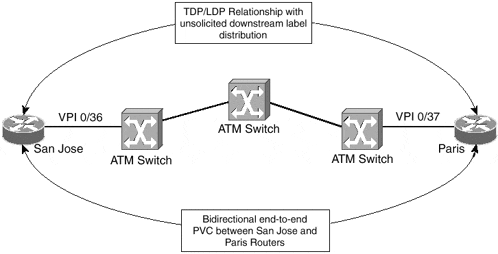
This type of connectivity, from an MPLS perspective, is essentially the same as described within the previous Frame Relay section. The label allocation scheme uses independent mode, and the distribution of labels uses unsolicited downstream. Figure 4-3 shows an example of this type of connectivity.
Figure 4-3. MPLS Connectivity Across ATM PVCs

You can see from Figure 4-3 that the San Jose and Paris routers are connected across a point-to-point ATM PVC. Again, using the show tag-switching tdp neighbor command confirms that unsolicited downstream label distribution is in effect across the interface and, therefore, MPLS is operating in Frame-mode. You can see this output in Example 4-3 and you can see the relevant configuration of the San Jose router in Example 4-4.
Example 4-3 Confirmation of TDP Relationship Between Two LSRs Across an ATM PVC
San Jose# show tag-switching tdp neighbor

Peer TDP Ident: 194.22.15.1:0; Local TDP Ident 194.22.15.2:0

     TCP connection: 194.22.15.1.711 ? 194.22.15.2.11064

     State: Oper; PIEs sent/rcvd: 6557/6559; ; Downstream

     Up time: 3d23h

     TDP discovery sources:

      ATM0/0/0.1

     Addresses bound to peer TDP Ident:

      146.4.1.17    196.7.25.1      194.22.15.1    10.2.1.13
Example 4-4 MPLS Across ATM PVC Router Configuration
interface ATM0/0/0

 no ip address

!

interface ATM0/0/0.1 point-to-point

 description ** interface to Paris

 ip address 146.4.1.18 255.255.255.252

 pvc 0/36

  encapsulation aal5snap

 !

 tag-switching ip
Note
Running MPLS across an ATM Forum PVC requires AAL5SNAP encapsulation on that PVC. AAL5MUX encapsulation does not work because packets of two different protocols (pure IP control packets and labeled data packets) are exchanged over the same VC. Chapter 2 details the specific encapsulation across ATM.
Frame-mode and Cell-mode MPLS Across the Same ATM Interface
It might be desirable in some deployments of the MPLS architecture to run both Frame-mode and Cell-mode MPLS across the same physical ATM interface, for example when linking two private MPLS-enabled ATM networks across a public ATM network that offers only ATM Forum PVC services. You can see how this feature can be used in the migration of an ATM network toward MPLS in the migration example in Chapter 6.
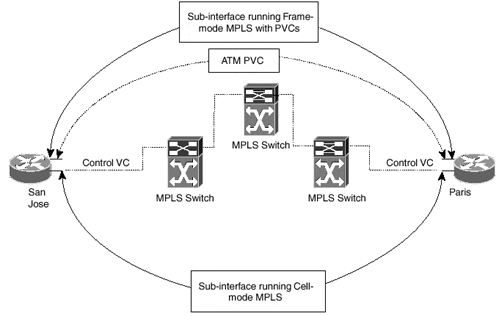
This type of connectivity is possible through the use of sub-interfaces with different sub-interface types on the router's ATM interface configuration. These sub-interfaces can be configured to run Cell-mode MPLS (sub-interface type tag-switching), or they can be configured to run Frame-mode (sub-interface type point-to-point). Figure 4-4 illustrates this technique.
The example topology in Figure 4-4 shows that the San Jose and Paris routers have a point-to-point PVC connection between them but they also run Cell-mode MPLS directly with the MPLS ATM switch. This is achieved through the use of two separate ATM sub-interfaces. Example 4-5 shows the configuration of the San Jose router in this environment.
Example 4-5 Configuration of Frame-mode and Cell-mode MPLS on the Same ATM Interface
interface ATM0/0/0

 no ip address

!

interface ATM0/0/0.1 point-to-point

 description ** ATM PVC interface to Paris

 ip address 146.4.1.18 255.255.255.252

 pvc 0/36

  encapsulation aal5snap

 !

 tag-switching ip

!

interface ATM0/0/0.2 tag-switching

 description ** cell-mode interface to adjacent ATM-LSR

 ip unnumbered Loopback0

 tag-switching ip
Figure 4-4. Frame-mode and Cell-mode MPLS Across the Same ATM Interface


