Chapter 3. Cell-mode MPLS Operation
In Chapter 2, "Frame-mode MPLS Operation," you saw how MPLS is run between Layer 3 switching devices (routers) across Frame-mode interfaces. The routers running MPLS exchange pure IP packets (for control protocols) as well as labeled IP packets (forwarded or non-adjacent locally sourced traffic) over the same link. They also perform label switching by examining the label header in front of the IP packet.
When trying to fit the MPLS architecture into the limitations of ATM technology, a number of obstacles must be overcome:
There is no mechanism for direct exchange of IP packets between two adjacent MPLS nodes over an ATM interface. All data exchange over an ATM interface must take place over an ATM virtual circuit (VC).
ATM switches cannot perform MPLS label lookup or Layer 3 lookup. The only capability of an ATM switch is to map the incoming VC in a cell to an outgoing VC and an outgoing interface.
Note
In the ATM world, a pair of values?the virtual path identifier (VPI) and the virtual circuit identifier (VCI)?identify the VC. These values are local to an incoming or outgoing interface; the same VPI/VCI value denotes a different VC when used on a different interface.
The VC lookup operation in an ATM switch is exceedingly simple: The incoming interface and the VPI/VCI value in the incoming cell are used to look up the outgoing interface and the outgoing VPI/VCI value.
The ATM technology design and architecture present a number of challenges to an ATM implementation of MPLS technology, all of which will be discussed in this chapter:
Control-plane IP packets cannot be exchanged directly over an ATM interface. A control VC must be established between adjacent MPLS nodes to exchange control-plane packets.
ATM switches cannot perform label lookup. The top label in the label stack must be translated into the VPI/VCI value.
ATM switches cannot perform Layer 3 lookup. The label allocation and distribution procedures must be modified to make sure that an ATM switch will never have to perform Layer 3 lookup.
Additional limitations of ATM technology become apparent in the area of loop detection and prevention techniques. These limitations and corresponding solutions will be discussed in Chapter 5, "Advanced MPLS Topics."
The ATM implementation of MPLS technology uses several terms that are specific to the ATM world and that will be used throughout this chapter:
Label Switching Controlled ATM interface (LC-ATM interface) is an interface on a router or an ATM switch in which the VPI/VCI value is assigned through MPLS control protocols (TDP or LDP).
ATM-LSR is an ATM switch that runs MPLS protocols on the control plane and performs MPLS forwarding between LC-ATM interfaces on the data plane by means of traditional ATM cell switching.
Frame-based LSR is an LSR that forwards complete frames between its interfaces. A typical example of a frame-based LSR is a traditional router. A frame-based LSR can also have a number of LC-ATM interfaces, but it performs only frame-based label switching based on label stack, not cell switching like an ATM-LSR.
ATM-LSR domain is a set of ATM-LSRs interconnected by LC-ATM interfaces.
ATM edge-LSR is a frame-based LSR with at least one LC-ATM interface.
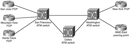
Throughout the chapter, a sample network (shown in Figure 3-1) will be used for configuration or debugging printouts. The network in this figure is identical to the network in Chapter 2, with the core routers being replaced by ATM switches. The IP addressing in this network is the same as the IP addressing in the SuperNet network of Chapter 2; refer to Chapter 2 for IP address assignment in the SuperCell network.
Figure 3-1. SuperCell Network?ATM Implementation


