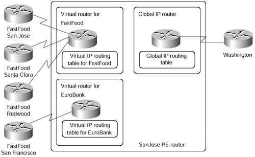
VPN Routing and Forwarding Tables
The overlapping addresses, usually resulting from usage of private IP addresses in customer networks, are one of the major obstacles to successful deployment of peer-to-peer VPN implementations. The MPLS/VPN technology provides an elegant solution to the dilemma: Each VPN has its own routing and forwarding table in the router, so any customer or site that belongs to that VPN is provided access only to the set of routes contained within that table. Any PE-router in an MPLS/VPN network thus contains a number of per-VPN routing tables and a global routing table that is used to reach other routers in the provider network, as well as external globally reachable destinations (for example, the rest of the Internet). Effectively, a number of virtual routers are created in a single physical router, as displayed in Figure 8-2 for the case of San Jose router of SuperCom network.
Note
The relationship between virtual private networks and VPN routing and forwarding tables as explained in the previous paragraph is a slight simplification of the actual relationship between these two concepts. Nevertheless, it is true in cases where each site (or customer) belongs only to one VPN. The additional complexity introduced by overlapping VPNs or sites belonging to more than one VPN is explained in the section "Overlapping Virtual Private Networks," later in this chapter.
The concept of virtual routers allows the customers to use either global or private IP address space in each VPN. Each customer site belongs to a particular VPN, so the only requirement is that the address space be unique within that VPN. Uniqueness of addresses is not required among VPNs except where two VPNs that share the same private address space want to communicate.
More structures are associated with each virtual router than just the virtual IP routing table:
A forwarding table that is derived from the routing table and is based on CEF technology.
A set of interfaces that use the derived forwarding table.
Rules that control the import and export of routes from and into the VPN routing table. These rules were introduced to support overlapping VPNs and are explained later in this chapter.
A set of routing protocols/peers, which inject information into the VPN routing table. This includes static routing.
Router variables associated with the routing protocol that is used to populate the VPN routing table.
Figure 8-2. Virtual Routers Created in a PE-router
The usage of these structures is explained in the rest of this chapter, and the detailed operation of each of them is explained in the next chapters.
The combination of the VPN IP routing table and associated VPN IP forwarding table is called VPN routing and forwarding instance (VRF).
Note
You might think that there is no difference between an IP routing table and an IP forwarding table?and usually that's true. In an MPLS environment, the only minor difference between them is the fact that the IP forwarding table also contains MPLS encapsulation information.
A major difference between the two tables arises in cases where an IP route refers to a next hop that is not directly connected. In that case, the routing table will contain the next-hop information, but not the outgoing interface or the IP address of the downstream router. The forwarding table will contain all the information needed to forward the packet toward the destination. For example, with the configuration in Example 8-1, the routing table lists the next hop for network 10.0.0.0/8 as 1.0.0.1 (as shown in Example 8-2), while the forwarding table contains the real next hop (the IP address of the downstream router), as shown in Example 8-3.
Example 8-1 Sample Configuration with Recursive IP Routing
ip route 10.0.0.0 255.0.0.0 1.0.0.1

ip route 1.0.0.1 255.255.255.255 2.0.0.2

!

interface serial 0

ip address 2.0.0.1 255.0.0.0
Example 8-2 IP Routing Table for the Recursive IP Routing Example
mpls router# show ip route

…

     1.0.0.0/32 is subnetted, 1 subnets

S       1.0.0.1 [1/0] via 2.0.0.2

C    2.0.0.0/8 is directly connected, Serial0

S    10.0.0.0/8 [1/0] via 1.0.0.1

…
Example 8-3 CEF Forwarding Table Entry for Recursive IP Routing Example
mpls router# show ip cef 10.0.0.0


10.0.0.0/8, version 87

0 packets, 0 bytes

  via 1.0.0.1, 0 dependencies, recursive

    next hop 2.0.0.2, Serial0 via 1.0.0.1/32
In the SuperCom case, the San Jose router contains three IP routing and forwarding tables?one table per customer and a global table used to forward non-VPN IP packets and to route VPN packets between PE-routers.


