Chapter 2. Frame-mode MPLS Operation
In Chapter 1, "Multiprotocol Label Switching (MPLS) Architecture Overview," you saw the overall MPLS architecture as well as the underlying concepts. This chapter focuses on one particular application: unicast destination-based IP routing in a pure router environment (also called Frame-mode MPLS because the labeled packets are exchanged as frames on Layer 2). Chapter 3, "Cell-mode MPLS Operation," focuses on the unicast destination-based IP routing in the ATM environment (also called Cell-mode MPLS because the labeled packets are transported as ATM cells).
This chapter first focuses on the MPLS data plane, assuming that the labels were somehow agreed upon between the routers. The next section explains the exact mechanisms used to distribute the labels between the routers, and the last section covers the interaction between label distribution protocols, the Interior Gateway Protocol (IGP), and the Border Gateway Protocol (BGP) in a service provider network.
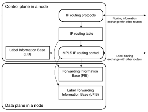
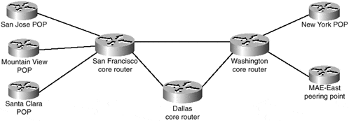
Throughout the chapter, we refer to the generic architecture of an MPLS Label Switch router (LSR), as shown in Figure 2-1, and use the sample service provider network (called SuperNet) shown in Figure 2-2 for any configuration or debugging printouts.
The SuperNet network uses unnumbered serial links based on loopback interfaces that have IP addresses from Table 2-1.
|
Router |
Loopback Interface |
|---|---|
|
San Jose |
172.16.1.1/32 |
|
Mountain View |
172.16.1.2/32 |
|
Santa Clara |
172.16.1.3/32 |
|
San Francisco |
172.16.1.4/32 |
|
Dallas |
172.16.2.1/32 |
|
Washington |
172.16.3.1/32 |
|
New York |
172.16.3.2/32 |
|
MAE-East |
172.16.4.1/32 |
Figure 2-1. Edge-LS R Architecture

Figure 2-2. SuperNet Service Provider Network


