Inter-provider VPN Solutions
The last connectivity option to consider is the case in which a VPN customer, or ISP customer, wants to obtain VPN service through multiple service providers. This situation will most likely arise because of geography?certain sites will need to attach to one service provider, and others will need to attach to another service provider. This means that transit between one site and another site may pass through multiple MPLS/VPN backbones. Within the MPLS/VPN architecture, this connectivity requirement is known as Multi-provider or inter-provider VPN.
The problem with this connectivity requirement is that VPN information needs to be passed between MPLS/VPN service providers so that they can route traffic for a particular VPN successfully. This type of service is not available with the description of the MPLS/VPN architecture that we have seen so far. A new mechanism is needed so that prefix and label exchange can occur in a scalable manner between MPLS/VPN domains. Figure 14-14 provides an illustration of a topology in which this type of connectivity may be required.
Figure 14-14. Inter-provider VPN Connectivity?Topology Example
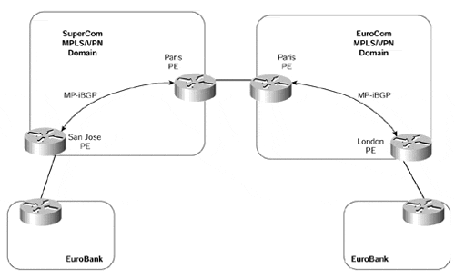
This sample topology shows that the EuroBank VPN customer has sites in San Jose and London. Because of the geography, the San Jose site attaches to the SuperCom MPLS/VPN backbone via the San Jose PE-router, and the London site attaches to the EuroCom MPLS/VPN backbone via the London PE-router. This type of connectivity requires inter-provider route exchange of VPN customer prefixes.
There are actually two ways to provide this type of inter-provider connectivity, although others may become available over time. The first is to exchange VPN-IPv4 prefixes/labels across the service provider MPLS/VPN domain boundaries. In our example, this would mean between the SuperCom Paris PE-router and the EuroCom Paris PE-router. The second option is to deploy multi-hop eBGP sessions between customer sites, or between service provider VPN-IPv4 route reflectors, and then exchange VPN-IPv4 prefixes/labels directly across these sessions.
Note
Future enhancement will allow for direct eBGP route exchange with labels and also the capability to turn off next-hop-self for eBGP sessions from route reflectors. Both of these features are necessary so that the next-hop PE addresses of any routes that are advertised across multi-hop MP-eBGP sessions can be passed between service providers without conversion to VPNv4 routes.
Inter-provider VPN?Exchange of VPN-IPv4 Across Boundaries
This first option allows the same functionality as the standard MPLS/VPN architecture that we have already seen, except that the customer is attached to multiple service providers instead of just one.
Each customer site attaches to its local MPLS/VPN backbone and exchanges routes, including all external routes, with the provider across its PE-to-CE link. Because the exchange of routing information between the customer and the MPLS/VPN backbone includes external routes, this solution is not really suitable in the situation where the customer is an ISP, for the same reasons that were discussed in the previous section.
These routes belong to VPN customers, so they are allocated labels by the service provider PE-router and are advertised across the MPLS/VPN backbone as VPN-IPv4 routes using MP-iBGP between PE-routers. Figure 14-15 shows the basic structure of this type of connectivity.
Figure 14-15. Inter-provider VPN?Exchange of VPN-IPv4 Between Service Providers
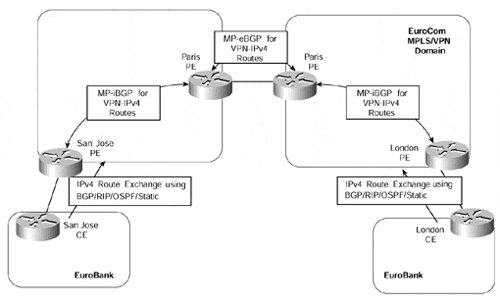
Figure 14-15 shows that each service provider establishes a direct MP-eBGP session with the other provider and exchanges VPN-IPv4 addresses with labels across this link. In the figure, this session is established between the two Paris PE-routers. Because these routers provide connectivity between two separate MPLS/VPN domains, we can refer to them as PE-ASBR routers. No IGP or LDP/TDP label distribution occurs across this link, so both service provider networks are completely separate. This means that they do not need to exchange any of their internal prefix or MPLS label information. The configurations for the PE-routers shown in Figure 14-15 can be seen in Example 14-2.
Example 14-2 Inter-provider VPN?Exchange of VPNv4 Across Service Provider Boundaries (Configuration Example)
SuperCom PE Routers


hostname San Jose

!

ip vrf EuroBank

 rd 1:27

 route-target export 100:27

 route-target import 100:27

!

interface Loopback0

 ip address 194.22.15.2 255.255.255.255

!

router bgp 1

 no bgp default ipv4-unicast

 neighbor 194.22.15.1 remote-as 1

 !

 address-family ipv4 vrf EuroBank

 redistribute connected

 redistribute static

 no auto-summary

 no synchronization

 exit-address-family

 !

 address-family vpnv4

 neighbor 194.22.15.1 activate

 neighbor 194.22.15.1 send-community extended

 exit-address-family


hostname Paris

!


interface Loopback0

 ip address 194.22.15.1 255.255.255.255

!

router bgp 1

 no bgp default ipv4-unicast

 no bgp default route-target filter

 neighbor 194.22.15.2 remote-as 1

 neighbor 195.26.19.1 remote-as 2

 !

 address-family ipv4 vrf EuroBank

 no auto-summary

 no synchronization

 exit-address-family

 !

 address-family vpnv4

 neighbor 195.26.19.1 activate

 neighbor 195.26.19.1 send-community extended

 neighbor 194.22.15.2 activate

 neighbor 194.22.15.2 next-hop-self

 neighbor 194.22.15.2 send-community extended

 exit-address-family


EuroCom PE Routers


hostname Paris

!


interface Loopback0

 ip address 195.26.19.1 255.255.255.255

!

router bgp 2

 no bgp default ipv4-unicast

 no bgp default route-target filter

 neighbor 195.26.19.2 remote-as 2

 neighbor 194.22.15.1 remote-as 1

 !

 address-family ipv4 vrf EuroBank

 no auto-summary

 no synchronization

 exit-address-family

 !

 address-family vpnv4

 neighbor 195.26.19.2 activate

 neighbor 195.26.19.2 next-hop-self

 neighbor 195.26.19.2 send-community extended

 neighbor 194.22.15.1 activate

 neighbor 194.22.15.1 send-community extended

 exit-address-family


hostname London

!

ip vrf EuroBank

 rd 1:27

 route-target export 100:27

 route-target import 100:27

!

interface Loopback0

 ip address 195.26.19.2 255.255.255.255

!

router bgp 2

 no bgp default ipv4-unicast

 neighbor 195.26.19.1 remote-as 2

 !

 address-family ipv4 vrf EuroBank

 redistribute connected

 no auto-summary

 no synchronization

 exit-address-family

 !

 address-family vpnv4

 neighbor 195.26.19.1 activate

 neighbor 195.26.19.1 send-community extended

 exit-address-family
Note
Notice within the configuration shown in Example 14-2 that you do not need to configure any VRFs on the border PE-routers. This is because the automatic route filtering feature, which we discussed in Chapter 9, "MPLS/VPN Architecture Operation," has been disabled through use of the no bgp default route-target filter command.
In the example shown in Figure 14-15, if the SuperCom San Jose PE-router advertised a route via MP-iBGP to the SuperCom Paris PE-router, then if this router advertised the route to the EuroCom Paris PE-router with the same VPN label, connectivity would be lost. This is because no LDP/TDP label distribution occurs across this link. Therefore, when a packet is forwarded by the EuroCom Paris PE-router toward the SuperCom network, the label stack will contain one entry. This entry will be the VPN label as received through MP-eBGP, but the SuperCom Paris PE-router will not know how to forward the packet because it did not allocate the label. This is the same situation that we saw in Chapter 12, "Advanced MPLS/VPN Topics," in our discussion of BGP confederations.
For this reason, when MP-eBGP is used between two PE-ASBR routers, the advertising PE-router allocates a new label for the route before it advertises it across the MP-eBGP session to the other PE-router. This behavior is enabled by default on an MP-eBGP session, but it can also be controlled by the next-hop-self command if the receiving PE-ASBR router wants to allocate a different label for use by its interior neighbors.
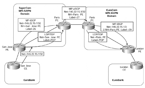
The interface that is used to establish the MP-eBGP session between the two service providers does not need to be associated with any VRF. This is because labels already will be assigned to the routes when learned via MP-eBGP. The label allocation for this type of connectivity can be seen in Figure 14-16.
Figure 14-16 shows that each of the inter-provider PE-routers?in this case, the SuperCom Paris and EuroCom Paris routers?allocates a new label to represent each VPN route that it receives across its internal MPLS/VPN domain.
Figure 14-16. Exchange of VPN-IPv4 Routes Between Service Providers (Label Allocation)
Note
Figure 14-16 shows only one link between PE-ASBR routers within each MPLS/VPN domain. Of course, this is a simplified topology to illustrate the techniques and label allocation, but in a real deployment of this architecture, the label stack within each MPLS/VPN domain will carry two labels: an internal label to reach the advertising PE-ASBR router, and a VPN label.
The relevant label assignments for all PE-routers are shown in Example 14-3.
Example 14-3 Inter-provider VPN?Label Assignment Example
EuroCom PE Routers


London# show ip bgp vpnv4 all tags


Network          Next Hop      In tag/Out tag

Route Distinguisher: 1:27 (EuroBank)

   146.22.15.1/32     195.26.19.l       notag/39


Paris# show ip bgp vpnv4 all tags


Network          Next Hop      In tag/Out tag

Route Distinguisher: 1:27 (EuroBank)

   146.22.15.1/32     10.2.1.10       39/27


SuperCom PE Routers


Paris# show ip bgp vpnv4 all tags


Network          Next Hop      In tag/Out tag

Route Distinguisher: 1:27 (EuroBank)

   146.22.15.1/32     194.22.15.2       27/26


San Jose# show ip bgp vpnv4 all tags


Network          Next Hop      In tag/Out tag

Route Distinguisher: 1:27 (EuroBank)

   146.22.15.1/32     0.0.0.0         26/aggregate(EuroBank)
Note
The allocation of a new label by the EuroCom Paris PE-ASBR router is not strictly necessary. This is because label switching will be successful even if this router does not allocate a new label, as long as a host route for the adjacent PE-ASBR router is contained within the IGP of the receiving MPLS/VPN backbone. Therefore, configuration of next-hop-self on this PE-router, in respect of routes that it advertises to internal MP-iBGP neighbors, can be disabled, if desired. However, this is not recommended because it implies that redistribution of peer addresses into the IGP must occur.
In our example, this means that a /32 route for the SuperCom Paris PE-ASBR interface address (which attaches to the EuroCom Paris PE-ASBR router) would need to be redistributed into the EuroCom MPLS/VPN domain. This /32 host route is created by default and does not need to be configured. However, it must be redistributed into the receiving service provider's IGP. Without this host route, label switching will fail because the interface between service providers is directly connected and next-hop-self is not performed on the receiving PE-ASBR router. As with any directly connected interface, the IGP label is popped one hop before the receiving PE-router. In our example, this would cause the EuroCom Paris PE-ASBR router to receive a packet with only the VPN label; because it did not allocate the label, label switching would fail.
This label is used across the inter-provider link and is swapped for the original label stack by the receiving PE-ASBR router. An example of this is shown in Figure 14-17. Again, for the sake of simplicity, only one hop across each MPLS/VPN domain is used; only the VPN labels are shown because the internal label will have been removed due to penultimate hopping. However, in a typical deployment, a two-level label stack will be required across each service provider network, one for the VPN label and the other to reach the egress PE for the destination of the packet.
Figure 14-17. Exchange of VPN-IPv4 Routes Between Service Providers (Traffic Flow)
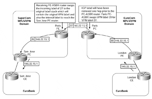
This figure shows that each inter-provider PE-ASBR router assigns its own label, which it associates with the relevant label stack to reach a particular VPN destination. Therefore, when a packet is sent from the EuroBank London site to prefix 146.22.15.1/32 in the EuroBank San Jose site, the labels that are used across the SuperCom and EuroCom MPLS/VPN domains are as shown in Figure 14-17.
Inter-provider VPN?Multi-hop eBGP Between Customer Sites
The second option with this type of connectivity is the direct exchange of VPN information between sites using MP-eBGP or MP-iBGP. This is the same scenario as with the hierarchical VPN solution that we saw previously, except that the session between customer sites may be eBGP rather than iBGP (unless, of course, each site uses the same ASN, in which case it will be iBGP). MP-eBGP will be used across the inter-provider session. If the session between VPN sites is eBGP, then BGP multi-hop must be used.
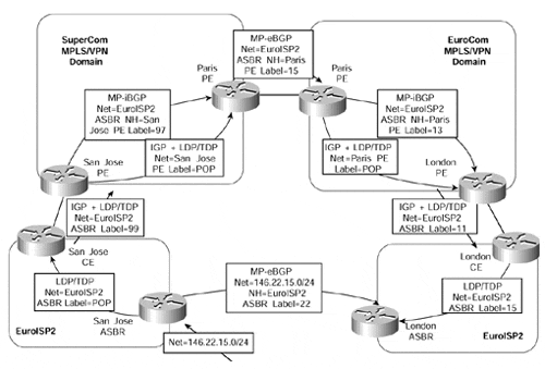
This connectivity option may be useful if the customer of the MPLS/VPN backbone is an ISP that wants to exchange large amounts of routes with other sites, and if some of those sites are attached to a separate MPLS/VPN service provider. An example topology for this type of connectivity can be seen in Figure 14-18.
Figure 14-18. Inter-provider VPN?Multi-hop eBGP Between Customer Sites
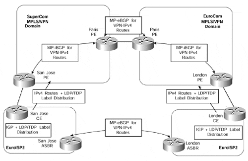
Figure 14-18 shows that ISP-customer external routes are exchanged between ISP sites through the use of MP-eBGP or MP-iBGP. The BGP next-hop addresses for these routes are exchanged with the MPLS/VPN backbone and then are advertised between service providers.
The label allocation for this type of connectivity is shown in Figure 14-19. Again, for simplicity, a one-hop MPLS/VPN backbone is shown for each of the service providers.
The label allocation is the same as shown in our example of the hierarchical VPN scenario. The only difference is that the customer routes, in this case, are advertised using MP-eBGP as opposed to MP-iBGP between sites. In addition, the BGP next-hop addresses are advertised between MPLS/VPN domains as VPN-IPv4 prefixes. Figure 14-20 shows the subsequent traffic flow for a packet sent from the EuroISP2 London site to a host on the 146.22.15.0/24 subnet.
Figure 14-19. Inter-provider VPN?Multihop eBGP Between Customer Sites (Label Allocation)
