Separate BGP Session Between PE- and CE-routers
Although the configuration of static routes for each VPN customer provides Internet connectivity to these customers through use of a default route, it may not be sufficient for certain network deployments, where the scalability of this solution may be restrictive.
Many implementations will require the capability to receive and advertise routes from the VPN customer sites directly with the Internet using BGP-4. The implications of this are that all Internet routes, or a subset of them, must be present on the PE-router that provides connectivity to the customer site that is receiving or sending these BGP-4 routes. This PE-router also needs to be capable of advertising the routes contained within the global routing table to the VPN customer site.
However, because these routes are not contained within the VRF of the customer VPN, a mechanism is needed to allow the PE to distribute routes from the global routing table (where the Internet routes reside) to the customer site, and to also recognize routes from the customer site that must be placed into the global table rather than the VRF. No mechanism in the MPLS/VPN implementation would give us the flexibility needed in this case, and the only way to implement the desired functionality is through a second interface to the customer, which is not part of any VRF and which belongs to the global routing table. The second interface is used to carry non-VPN specific routes between the PE- and CE-routers.
This second interface may be a separate physical interface, but it could also be a logical interface (such as a subinterface created over a Frame Relay DLCI) or a tunnel, allowing the customer and the service provider to exchange VPN and Internet data over the same physical infrastructure. A normal BGP-4 session needs to be established between the PE- and CE-routers across this second interface, and the CE-router must originate customer routes that the PE-router will propagate to the rest of the Internet from the global routing table. An example of this type of connectivity is shown in Figure 12-23.
Figure 12-23. Internet Connectivity?Multiple (Sub)interface Model
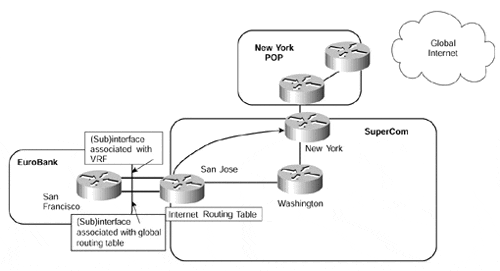
Figure 12-23 shows that two interfaces are present between the EuroBank San Francisco CE-router and the SuperCom San Jose PE-router. In this case, they are provided through use of (sub)interfaces?one of these interfaces is associated with the EuroBank VRF, and the other one is not. Using this configuration, the EuroBank CE-router can learn Internet routes via one (sub)interface and VPN routes through the other.
It is also possible to run just one interface between the PE- and CE-routers, but to configure a tunnel to carry the VPN routes. This method is illustrated in Figure 12-24.
Note
Running an MPLS/VPN PE-CE link across an interface that gives the customers their Internet access is potentially a large security problem. Unless you deploy very strict filtering on PE- and CE-routers, it's very easy for an intruder connected to the Internet to insert packets into your VPN. This design is thus best avoided.
Figure 12-24. Internet Connectivity?Tunnel Interface for VPN Routes
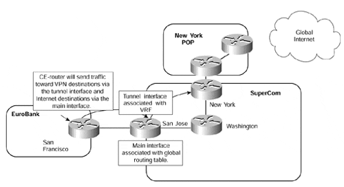
Figure 12-24 shows that the CE-router is capable of routing traffic based on the interface that the route is learned from. If a route is learned across the main interface (and these will include Internet routes), then the San Francisco CE-router will send packets via this interface. However, if the route is learned from across the tunnel interface (and all VPN specific routes will be), the San Francisco CE-router will send traffic across the tunnel. On the San Jose PE-router, packets that are received across the main interface are routed using the global routing table information, and packets received across the tunnel are routed using the EuroBank VRF forwarding table.
In certain circumstances, some MPLS/VPN solution providers may want to provide full Internet routes to different customers that have been learned from different sources. The reason for this may be administrative or policy-based, or may be simply to satisfy specific customer routing needs. The implications of this requirement are quite complex. In normal operation, Internet routes will be sent to all VPN customers with the next-hop of the advertising PE-router and the AS_PATH information of the best routes that have been learned from one or multiple Internet exit points. However, certain VPN customers may want to learn Internet routes from the same advertising PE-router but with different AS_PATH information that has been learned from another Internet exit point (this may or may not be the best path, as far as the PE-router is concerned). Figure 12-25 provides an example of this requirement.
Figure 12-25. Internet Connectivity Through Multiple Exit Points
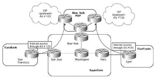
Figure 12-25 shows that two separate VPN customers, EuroBank and FastFoods, require Internet access through separate exit points within the SuperCom backbone. The actual exit point that a particular VRF will use can be resolved through the use of static default routes, as described in the previous section. However, this would not allow each VPN customer to learn or advertise routes directly through BGP-4. This means that a further mechanism is needed so that the PE-router will route traffic for different VPNs to different exit points.
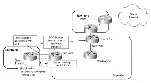
In a normal routing environment, this requirement presents a problem. The PE-router will pick the best BGP route and will advertise this best route to its BGP neighbors, which would include all VPN customers that require direct Internet access. To be able to choose which exit point to use, we could try to set the BGP next-hop of any routes that are advertised from the PE- to the CE-router as the address of the desired Internet exit point. This can be seen in Figure 12-26.
Figure 12-26 shows that the EuroBank CE-router runs two separate interfaces to the PE-router. The next-hop of any Internet routes has been reset at the PE through use of a route map, and this next-hop address has been distributed to the CE by advertisement across the VRF interface. The exit point is contained within the VRF via a static route, so all traffic that matches this BGP next-hop will be sent over the VRF interface and then will use the default route within the VRF to direct the traffic to the desired Internet exit point.
Figure 12-26. Resetting BGP Next-hop at PE-router
Note
It is worth noting that with this solution, traffic flow is asymmetric. Traffic travelling from a VPN site to the Internet will take the VRF interface, while the return traffic will use the global interface.
A configuration example for this connectivity option can be seen in Example 12-14.
Example 12-14 Resetting BGP Next-hop Configuration Example
hostname San Francisco

!

interface Serial1/0

 ip address 10.2.1.6  255.255.255.252

!

interface Ethernet6/0

 ip address 10.2.1.25 255.255.255.252

!

router bgp 2

 neighbor 10.2.1.5 remote-as 1

 neighbor 10.2.1.5 update-source Loopback0

 neighbor 10.2.1.26 remote-as 1

 neighbor 10.2.1.26 update-source Loopback0

!


hostname San Jose

!

ip vrf EuroBank

 rd 1:27

 route-target both 100:27

!

interface Serial0/0/0

 ip address 10.2.1.5 255.255.255.252

!

interface Ethernet0/1/0

 ip forwarding vrf EuroBank

 ip address 10.2.1.26 255.255.255.252

!

router bgp 1

 no synchronization

 no bgp default ipv4-unicast

 neighbor 10.2.1.5 remote-as 2

 neighbor 10.2.1.5 activate

 neighbor 10.2.1.5 route-map EuroBank out

 neighbor 194.22.15.3 remote-as 1

 neighbor 194.22.15.3 update-source Loopback0

 neighbor 194.22.15.3 activate

 !

 address-family ipv4 vrf EuroBank

 redistribute connected

 redistribute static

 neighbor 10.2.1.25 remote-as 2

 neighbor 10.2.1.25 activate

 no auto-summary

 no synchronization

 exit-address-family

 !

route-map EuroBank permit 10

 set ip next-hop 194.22.15.3

!

ip route vrf EuroBank 0.0.0.0 0.0.0.0 194.22.15.3 global

ip route vrf EuroBank 194.22.15.3 255.255.255.255 10.1.1.13 global
The problem with this configuration is that no BGP routes will be accepted across the interface because the next-hop address will not be a directly connected interface. Of course, this could be remedied by changing the next-hop of the route on the CE-router when it receives the route. Example 12-15 shows debug output that confirms this.
Example 12-15 Reset BGP Next-hop debug
San Francisco# debug ip bgp updates


BGP(0): 10.2.1.5 rcv UPDATE about 197.1.1.1/32 -- DENIED due to: non-connected next-

hop;

BGP: 10.2.1.5 Non-local next-hop 194.22.15.3
Even though this approach is possible, it has two main drawbacks. First, two separate interfaces (or logical/[sub]interfaces) are required. Second, it does not address the AS_PATH information issue?we will potentially lose the desired information if the route via our selected exit point is not chosen as the best path via the BGP process on the PE-router.
To address this type of connectivity requirement so that only one interface is used and the AS_PATH information is maintained, the use of the eBGP multihop feature is required. With this feature, we can exchange VPN customer Internet routes directly with the exit point and make use of a default route within the VRF to direct all Internet traffic to this exit point without having to reset the BGP next-hop of the routes. Figure 12-27 provides an illustration of this technique.
Figure 12-27. Use of eBGP Multihop for Internet Connectivity
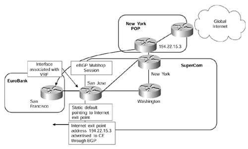
Figure 12-27 shows that the EuroBank San Francisco router runs a direct eBGP multihop session with the desired Internet exit point. The address used for this session, and the BGP next-hop of all routes, is placed into the EuroBank VRF (through a static route) and is advertised across the PE-to-CE BGP session. Reachability of the CE-router must also be given to the Internet gateway router. The relevant configuration of the San Francisco and San Jose routers is illustrated in Example 12-16.
Example 12-16 Use of eBGP Multihop Configuration Example
hostname San Francisco

!

interface Loopback0

 ip address 1.1.1.1 255.255.255.255

!

router bgp 2

 neighbor 194.22.15.3 remote-as 1

 neighbor 194.22.15.3 ebgp-multihop 255

 neighbor 194.22.15.3 update-source Loopback0

 neighbor 10.2.1.26 remote-as 1

 neighbor 10.2.1.26 update-source Loopback0

 neighbor 10.2.1.26 activate

!


hostname San Jose

!

ip vrf EuroBank

 rd 1:27

 route-target both 100:27

!

router bgp 1

 no synchronization

 no bgp default ipv4-unicast

 neighbor 194.22.15.3 remote-as 1

 neighbor 194.22.15.3 update-source Loopback0

 neighbor 194.22.15.3 activate

 !

 address-family ipv4 vrf EuroBank

 redistribute connected

 redistribute static

 neighbor 10.2.1.25 remote-as 2

 neighbor 10.2.1.25 activate

 no auto-summary

 no synchronization

 exit-address-family

 !

 address-family vpnv4

 neighbor 194.22.15.3 activate

 neighbor 194.22.15.3 send-community extended

 exit-address-family

!

! static route pointing to San Francisco CE Loopback so that it can be

! redistributed into the IGP so that the Internet exit point can reach

! the eBGP multihop peering address

!

ip route 1.1.1.1 255.255.255.255 Serial0/0/0

!

! static default route for EuroBank VRF pointing to Internet exit point

! loopback address

!

ip route vrf EuroBank 0.0.0.0 0.0.0.0 194.22.15.3 global

!

! static route pointing to the eBGP multihop peering address of the

! Internet exit point so that the CE-router is able to reach it. This

! static route will be advertised toward the CE-router

!

ip route vrf EuroBank 194.22.15.3 255.255.255.255 10.1.1.13 global
The eBGP multihop operation can be summarized as follows:
The CE-router is configured with a BGP session to the Internet exit point using eBGP multihop. The peer address for this session should be placed into the VRF through use of a static route. The BGP next-hop address for all routes that will be learned from this peer should also be within the VRF.
The CE-router has a further BGP session with the PE-router via the VRF interface. This is used to learn the BGP next-hop for all the routes and also the peer address of the eBGP multihop session. This need not necessarily be BGP?it could be any other protocol that is supported on a PE-to-CE link.
The CE-router receives routes from the Internet exit point (full or partial) with a next-hop that corresponds to the Internet exit point.
The CE-router forwards all Internet traffic toward the VRF interface of the PE-router because this is where the BGP next-hop address has been learned.
The PE-router has a default route within the VRF routing table that points to the Internet exit point.


