Typical VPN Network Topologies
The VPN topology required by an organization should be dictated by the business problems the organization is trying to solve. However, several well-known topologies appear so often that they deserve to be discussed here. As you can see, the same topologies solve a variety of different business issues in different vertical markets or industries.
The VPN topologies discussed here can be split into three major categories:
Topologies influenced by the overlay VPN model, which include hub-and-spoke topology, partial or full-mesh topology, and hybrid topology.
Extranet topologies, which include any-to-any Extranet and Central Services Extranet.
Special-purpose topologies, such as VPDN backbone and Managed Network topology.
Hub-and-spoke Topology
The most commonly encountered topology is a hub-and-spoke topology, where a number of remote offices (spokes) are connected to a central site (hub), similar to the setup in Figure 7-10. The remote offices usually can exchange data (there are no explicit security restrictions on inter-office traffic), but the amount of data exchanged between them is negligible. The hub-and-spoke topology is used typically in organizations with strict hierarchical structures, for example, banks, governments, retail stores, international organizations with small in-country offices, and so on.
Note
When deploying VPNs based on Layer 2 technologies, such as Frame Relay or ATM, the hub-and-spoke VPN topology is more common than you might expect. This is based purely on business needs due to higher costs or increased routing complexity associated with other topologies that use these types of technologies. In other words, there are many examples where the customer could benefit from a different topology but has nonetheless chosen the hub-and-spoke topology for cost or complexity reasons.
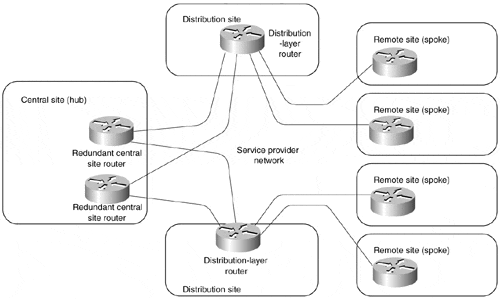
With increased redundancy requirements, the simple hub-and-spoke topology from Figure 7-10 often is enhanced with an additional router at the central site (shown in Figure 7-11) or with a backup central site, which is then linked with the primary central site through a higher-speed connection (shown in Figure 7-12).
Figure 7-10. Hub-and-spoke Topology
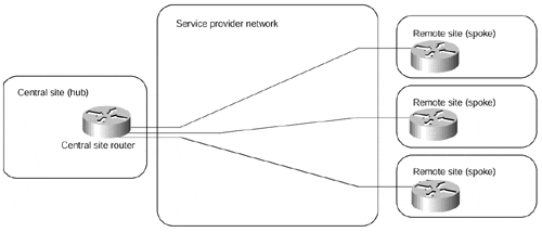
Figure 7-11. Hub-and-spoke Topology with Two Central Routers
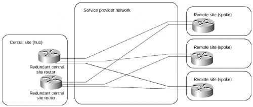
Implementing redundant hub-and-spoke topology with an overlay VC?based VPN model always poses a number of challenges. Each hub site requires a VC to at least two central routers. These VCs could be provisioned in primary-backup configuration or in load-sharing configuration with a number of drawbacks of one or the other solution:
In primary-backup configuration, the backup VC is unused while the primary VC is active, resulting in unnecessary expenses incurred by the customer.
In load-sharing configuration, the spoke site encounters reduced throughput if one of the VCs (or one of the central routers) fails. The load-sharing configuration is also not appropriate for the topologies with a backup central site similar to the one in Figure 7-12.
Figure 7-12. Hub-and-spoke Topology with Two Central Sites
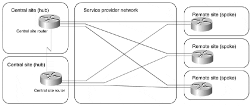
The higher-quality service providers try to meet the redundancy requirements of their customers with an enhanced service offering called shadow PVC. With a shadow PVC, the customer gets two virtual circuits for the price of one on the condition that they can use only one VC for data traffic at a time (a small amount of traffic is allowed on the second PVC to enable routing protocol exchanges over the second PVC).
Redundancy requirements can further complicate hub-and-spoke topology with the introduction of dial-backup features. The dial backup solution implemented within the service provider network (for example, an ISDN connection backing up a Frame-Relay leased line, as shown in Figure 7-13) is transparent to the customer, but it does not offer true end-to-end redundancy because it cannot detect all potential failures (for example, CPE or routing protocol failures). The true end-to-end redundancy in an overlay VPN model can be achieved only by CPE devices establishing a dial-up connection outside the VPN space.
Usually, simple hub-and-spoke topology transforms into multilevel topology as the network grows. The multilevel topology can be a recursive hub-and-spoke topology, similar to the one shown in Figure 7-14, or a hybrid topology, which is discussed later in this section. The network restructuring can be triggered by scalability restrictions of IP routing protocols or by application-level scalability issues (for example, the introduction of a three-tier client-server approach).
Figure 7-13. Dial Backup Solution Within Service Provider Network
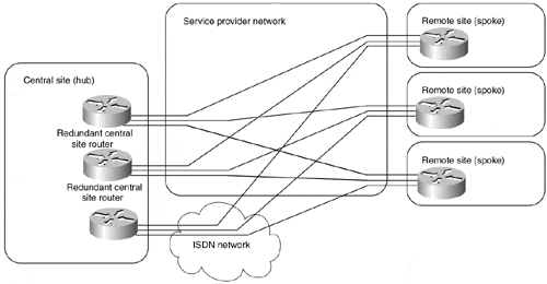
Figure 7-14. Multilevel Hub-and-spoke Topology
The hub-and-spoke topology implemented with an overlay VPN model is well suited to environments where the remote offices mostly exchange data with the central sites and not with each other, as the data exchanged between the remote offices always gets transported via the central site. If the amount of data exchanged between the remote offices represents a significant proportion of the overall network traffic, partial-mesh or full-mesh topology might be more appropriate.
Partial- or Full-mesh Topology
Not all customers can implement their networks with the hub-and-spoke topology discussed in the previous section for a variety of reasons, for example:
The organization might be less hierarchical in structure, requiring data exchange between various points in the organization.
The applications used in the organization need peer-to-peer communication (for example, messaging or collaboration systems).
For some multinational corporations, the cost of hub-and-spoke topology might be excessive due to the high cost of international links.
In these cases, the overlay VPN model best suited to the organization's needs would be a partial-mesh model, where the sites in the VPN are connected by VCs dictated by traffic requirements (which eventually are dictated by business needs). If not all sites have direct connectivity to all other sites (like the example in Figure 7-15), the topology is called a partial mesh; if every site has a direct connection to every other site, the topology is called a full mesh.
Note
Not many full-mesh networks are implemented due to the very high cost of this approach and the complexity introduced by the high number of VCs. With this type of topology, the number of VCs = [(n?1) x n)÷ 2] where n is equal to the number of attached devices.
Most of the customers have to settle for a partial mesh topology, which usually is affected by compromises and external parameters, such as link availability and the cost of VCs.
Figure 7-15. Partial-mesh Example

Provisioning a full-mesh topology is pretty simple?you just need a traffic matrix indicating the bandwidth required between a pair of sites in the VPN and you can start ordering the VCs from the service provider. Provisioning a partial mesh, on the other hand, can be a real challenge, as you have to do the following:
Figure out the traffic matrix.
Propose a partial-mesh topology based on a traffic matrix (for example, install a VC only between sites with high traffic requirements) and redundancy requirements.
Determine exactly over which VCs the traffic between any two sites will flow. This step also might involve routing protocol tuning to make sure the traffic flows over the proper VCs.
Size the VCs according to the traffic matrix and the traffic aggregation achieved over the VCs.
Note
The routing protocol issues in larger (usually multinational) partial meshes can grow to the proportion where it's extremely hard to predict the traffic flows without using such advanced simulation tools as Netsys. It is not unheard of to see customers who are forced to migrate to Border Gateway Protocol (BGP) just to handle the traffic engineering problems in their partial-mesh topologies.
Hybrid Topology
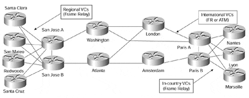
Large VPN networks built with an overlay VPN model tend to combine hub-and-spoke topology with the partial-mesh topology. For example, a large multinational organization might have access networks in each country implemented with a hub-and-spoke topology, whereas the international core network would be implemented with a partial-mesh topology. Figure 7-16 shows an example of such an organization.
Figure 7-16. Hybrid Topology Example
The best approach to the hybrid topology design is to follow the modular network design approach:
Split the overall network into core, distribution, and access networks.
Design the core and access parts of the network individually (for example, dual hub-and-spoke with dial backup in the access network, partial mesh in the core network).
Connect the core and access networks through the distribution layer in a way that isolates them as much as possible. For example, a local loop failure in a remote office somewhere should not be propagated into the core network. Likewise, the remote office routers should not see a failure of one of the international links.
Simple Extranet Topology
The Intranet topologies discussed so far are concerned mostly with the physical and logical topology of the VPN network, as dictated by the VC technology by which the overlay VPN model is implemented. In the extranet topologies, we focus more on the security requirements of the VPN network, which then can be implemented with a number of different topologies, either with the overlay or peer-to-peer VPN model.
The traditional extranet topology would be an extranet allowing a number of companies to perform any-to-any data exchange. The examples could include communities of interest (for example, airline companies, airplane manufacturers, and so on) or supply chain (for example, car manufacturer and all its suppliers).
The data in such an extranet can be exchanged between any numbers of sites?the extranet itself imposes no restriction on the data exchange. Usually, each site is responsible for its own security, traffic filtering, and firewalling. The only reason to use an extranet instead of the public Internet is quality of service guarantees and sensitivity of the data exchanged over such a VPN network, which still is more resilient to data capture attacks than the generic Internet.
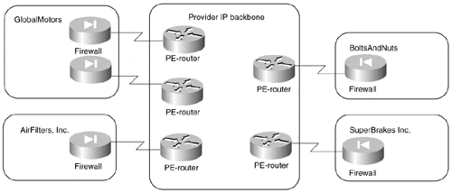
If the Extranet is implemented by a peer-to-peer VPN model (like the example Extranet in Figure 7-17), each organization specifies only how much traffic it's going to receive and send from each of its sites; thus, the provisioning on the customer and service provider side is very simple and effective.
Figure 7-17. Sample Extranet Implemented with Peer-to-peer VPN Model
In the overlay VPN model, however, the traffic between sites is exchanged over point-to-point VCs, similar to the example in Figure 7-18.
Figure 7-18. Sample Extranet Implemented with Overlay VPN Model
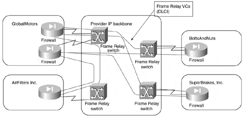
In the extranet topology similar to that in Figure 7-18, each participating organization usually pays for the VCs it uses. Obviously, only the most necessary VCs are installed to minimize the cost. Furthermore, participants in such a VPN would try to prevent transit traffic between other participants from flowing over VCs for which they pay, usually resulting in partial connectivity between the sites in the extranet and sometimes even resulting in interesting routing problems. The peer-to-peer VPN model is therefore the preferred way of implementing an any-to-any extranet.
Central-services Extranet
Extranets linking organizations that belong to the same community of interest are often pretty open, allowing any-to-any connectivity between the organizations. Dedicated-purpose extranets (for example, a supply chain management network linking a large organization with all its suppliers) tend to be more centralized and allow communication only between the organization sponsoring the extranet and all other participants, resembling the example shown in Figure 7-19.
Other examples of such an extranet include stock exchange networks, where every broker can communicate with the stock exchange, but not with other brokers or financial networks built in some countries between the central bank and the commercial banks. Although the purposes of such extranets can vary widely, they all share a common concept: a number of different users receive access to a central service (application, server, site, network, and so on).
Figure 7-19. Supply Chain Management Extranet
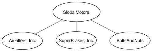
The security in the central services extranet typically is provided by the central organization sponsoring the extranet. Other participants with mission-critical internal networks (for example, stock brokers or commercial banks) also might want to implement their own security measures (for example, a firewall between their internal network and the extranet).
Similar to any other VPN network, the central services extranet can be implemented with either peer-to-peer or overlay VPN model. In this case, however, the peer-to-peer model has definitive disadvantages, because the service provider must take great care that the participants of the extranet cannot reach each other.
The implementation of the central services extranet by an overlay VPN model, on the contrary, is extremely straightforward:
VCs between all the participants and the central site are provisioned. The size of each VC corresponds to the traffic requirements between the participant and the central site.
The central site announces subnets available only at the central site to the other participants.
The central site filters traffic received by other participants to make sure a routing problem or purposeful theft-of-service attack does not influence the stability of the VPN.
Following these three steps, the VPN network from Figure 7-19 is transformed into a VC topology in Figure 7-18.
Note
Under the any-to-any extranet model, the network in Figure 7-18 would have a limited number of VCs (resulting in a redundant hub-and-spoke topology) due to cost constraints. Under the central services extranet model, the same VPN would have the same number of VCs due to security restrictions. This example thus represents an interesting case where a number of different requirements can dictate the same VC topology.
A slightly more complex central services extranet topology might contain a number of servers, dispersed across several sites, and a number of client sites accessing those servers, similar to the setup in Figure 7-20. Typical examples that would require this topology are Voice over IP networks, where a number of users access common gateways in different cities (or countries) but are not allowed to see each other.
Figure 7-20. Central Services Extranet with a Large Number of Server Sites
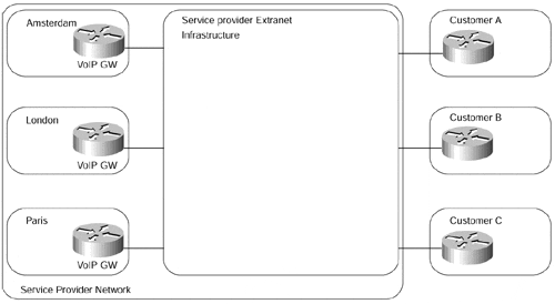
Such an extranet also can be implemented with either the peer-to-peer VPN model or the overlay VPN model. The number of VCs required in the overlay VPN model (a separate VC is required from each client site to each server site) and the corresponding provisioning complexity usually prevents the deployment of an overlay VPN model in these scenarios. A more manageable setup would use either a peer-to-peer model or a combination of both models, as illustrated in Figure 7-21.
Figure 7-21. Combination of Peer-to-peer VPN with Overlay VPN

Logically, the network in Figure 7-21 uses a peer-to-peer VPN model, with distribution routers acting as PE routers of the peer-to-peer model. The actual physical topology differs from the logical view: The distribution routers are linked with the customer sites (CE routers) through the overlay VPN model (for example, Frame Relay network).
VPDN Topology
The Virtual Private Dial-up Network (VPDN) service (also described in the section, "Business Problem-based VPN Classification," earlier in this chapter) usually is implemented by tunneling PPP frames exchanged between the dial-up user and his home gateway in IP packets exchanged between the network access server, as shown in Figure 7-22.
The dial-up user and the home gateway establish IP (or IPX, Appletalk, and so on) connectivity over the tunneled PPP link and exchange data packets over it. Figure 7-23 details the protocol stack used between various parts of the VPDN solution.
Figure 7-22. End-to-end Connectivity in a VPDN Solution
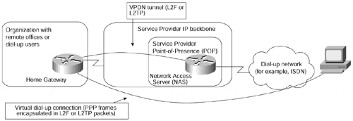
Figure 7-23. Protocol Stack in a VPDN Solution

Every VPDN solution requires an underlying IP infrastructure to exchange tunneled PPP frames between the NAS and the home gateway. In the simplest possible scenario, the public Internet can be used as the necessary infrastructure. When the security requirements are stricter, a virtual private network could be built to exchange the encapsulated PPP frames. The resulting structure is thought to be complex by some network designers, because they try to understand the whole picture in all details at once. As always, the complexity can be reduced greatly through proper decoupling:
The NAS and the home gateway use whatever IP infrastructure is available to exchange the VPDN data, which can be thought of as an application sitting on the top of the IP stack. Consequently, the internal structure of the underlying IP network does not affect the exchange of the application data, and the contents of the application data (IP packets in PPP frames encapsulated in a VPDN envelope) does not interact with the routers providing the IP service.
The underlying IP network is effectively a central services extranet with many server sites (Network Access Servers) and a home gateway acting as client sites. This infrastructure can be implemented in any number of ways, from pure overlay VPN model to pure peer-to-peer model.
Managed Network VPN Topology
The last VPN topology discussed in this chapter is the topology used by service providers to manage the customer-premises routers in a managed network service (see also the comments on the managed network service in the section, "Peer-to-peer VPN Model," earlier in this chapter). In a typical setup, shown in Figure 7-24, the service provider provisions a number of routers at customer sites, connecting them through VCs implemented with Frame Relay or ATM and builds a separate hub-and-spoke topology connecting every customer router with the Network Management Center (NMC).
Figure 7-24. Typical Managed Network Topology
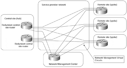
The VPN topology used in the customer part of the network can be any topology supported with the underlying VPN model, ranging from hub-and-spoke to full-mesh topology. The topology used in the CPE management part of the network effectively would be a central services extranet topology with the customer routers acting as clients and the Network Management Center being the central site of the management extranet.
As already explained in the Central-services Extranet section earlier in this chapter, such a topology is easiest to implement with a hub-and-spoke topology of the overlay VPN model, which also explains why most Managed Network service providers use the setup in Figure 7-24.
Note
The Managed Network topology can also be implemented with various peer-to-peer VPN technologies, although it's not as simple as with the overlay VPN model.Chapter 11, "Advanced MPLS/VPN Topologies," describes an example of a managed network implemented with MPLS/VPN technology.


