Propagation of VPN Routing Information in the Provider Network
The previous sections have explained MPLS/VPN architecture from a single PE-router standpoint. Two issues have yet to be addressed:
How will the PE-routers exchange information about VPN customers and VPN routes between themselves?
How will the PE-routers forward packets originated in customer VPNs?
This section addresses inter-PE routing; the next section briefly describes the forwarding mechanism.
Two fundamentally different ways exist for approaching the VPN route exchange between PE-routers:
The PE-routers could run a different routing algorithm for each VPN. For example, a copy of OSPF or EIGRP could be run for each VPN. This solution would face serious scalability problems in service provider networks with a large number of VPNs. It would also face interesting design challenges when asked to provide support for overlapping VPNs.
The PE-routers run a single routing protocol to exchange all VPN routes. To support overlapping address spaces of VPN customers, the IP addresses used by the VPN customers must be augmented with additional information to make them unique.
Note
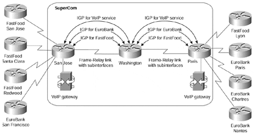
To illustrate the scalability issues that might arise from deploying one routing algorithm per VPN, consider the case where the SuperCom network would have to support more than 100 VPN customers connected to the San Jose and Paris routers with OSPF as the routing protocol. The PE-routers in the SuperCom network would run more than 100 independent copies of OSPF routing process (if that were technically possible), with each copy sending hello packets and periodic refreshments over the network. Because you cannot run more than one copy of OSPF over the same link, you would have to configure per-VPN subinterfaces (for example, using Frame Relay encapsulation) on the link between San Jose (or Paris) and Washington, resulting in an extremely complex network similar to the one shown in Figure 8-5. You would also have to run 100 different SPF algorithms and maintain 100 separate topology databases in the service provider routers.
The second approach was chosen as the building block of MPLS/VPN technology. IP subnets advertised by the CE-routers to the PE-routers are augmented with a 64-bit prefix called a route distinguisher to make them unique. The resulting 96-bit addresses are then exchanged between the PE-routers using a special address family of Multiprotocol BGP (hereby referred to as MP-BGP). There were several reasons for choosing BGP as the routing protocol used to transport VPN routes:
The number of VPN routes in a network can become very large. BGP is the only routing protocol that can support a very large number of routes.
BGP, EIGRP, and IS-IS are the only routing protocols that are multiprotocol by design (all of them can carry routing information for a number of different address families). IS-IS and EIGRP, however, do not scale to the same number of routes as BGP. BGP is also designed to exchange information between routers that are not directly connected. This BGP feature supports keeping VPN routing information out of the provider core routers (P-routers).
GP can carry any information attached to a route as an optional BGP attribute. What's more, you can define additional attributes that will be transparently forwarded by any BGP router that does not understand them. This property of BGP makes propagation of route targets between PE-routers extremely simple.
Figure 8-5. SuperCom Network with One IGP per VPN

Multiprotocol BGP in the SuperCom Network
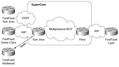
To illustrate the interaction of per-VPN routing protocols with the MP-BGP used in the service provider network core, consider the case of the FastFood customer in the SuperCom network. Let's assume that the San Jose site is using OSPF to interact with the SuperCom backbone, the Lyon and Santa Clara sites are using RIP, and the Redwood site is using no routing protocol?there is a static route configured on the San Jose PE-router and the default route configured on the Redwood router. The routing protocols used in FastFood VPN are shown in Figure 8-6.
Note
The Washington router (the P-router in the SuperCom network) is not involved in the MP-BGP. As you'll see in the next section, the forwarding model used in MPLS/VPN does not require the P-routers to make any routing decisions based on VPN addresses; they just forward packets based on the label value attached to the packet. The P-routers, therefore, do not need to carry the VPN routes, resulting in even better scalability.
Figure 8-6. Routing Protocols Used in FastFood VPN

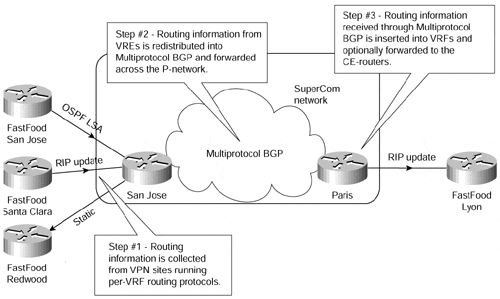
The San Jose PE-router collects routing information from the San Jose site using a per-VPN OSPF process. Similarly, the information from the Santa Clara site is collected using a per-VPN RIP process. This process is marked as Step 1 in Figure 8-7.
Note
The routing protocol used within a VPN network must be limited to the VPN in question. If the same routing protocol would be used in different VPNs, the possibility of using overlapping IP addresses between VPNs would be lost, and there would be potential route leakage between VPNs.
To support overlapping VPNs, the routing protocol must be limited to a single VPN routing and forwarding (VRF) table. Each PE-router must be configured so that any routing information learnt from an interface can be associated with a particular VRF. This is done through the standard routing protocol process and is known as the routing context. A separate routing context is used per VRF.
Some routing protocols (for example, RIP) support several instances (or routing contexts) of the same protocol, with each instance running in a different VRF. Other protocols (for example, OSPF) require a separate copy of the routing protocol process for each VRF.
The information gathered by various routing protocols in the San Jose PE-router, as well as the static routes configured on the San Jose router, is redistributed into MP-BGP. VPN addresses are augmented with the route distinguishers at the moment of redistribution. The route export route target specified in the originating VRF is also attached to the route. The resulting 96-bit routing information is propagated by MP-BGP to the Paris router (Step 2 in Figure 8-7).
Figure 8-7. Routing Protocol Operation in SuperCom Network

Warning
The redistribution of the per-VPN routing information into MP-BGP is not automatic and must be manually configured on the router for each VRF (see Chapter 9, "MPLS/VPN Architecture Operation," for further details of this configuration), unless this information was learned from the customer via BGP. The omission of manual redistribution into MP-BGP is one of the most common configuration errors in MPLS/VPN deployment.
The Paris router, after receiving MP-BGP routes, inserts the received routes into various VRF tables based on the route target attribute attached to each individual route. The route distinguisher is dropped from the 96-bit route when the route is inserted into the VRF, resulting yet again in a traditional IP route. Finally, the routing information received through BGP is redistributed into the RIP process and is passed on to the Lyon site through RIP updates (Step 3 in Figure 8-7).
Warning
Similar to the redistribution of VRF routes into MP-BGP, the redistribution of routes received over the service provider backbone back into the per-VRF routing process is not automatic, unless this process is BGP; it must be manually configured if the redistribution is required by the routing design.
Contrary to the traditional BGP operation in which the internal BGP routes are not allowed to be redistributed into other routing protocols, this restriction is lifted in the MPLS/VPN environment. The VPN routes received by a PE-router through an internal MP-BGP session from another PE-router can be redistributed into other routing protocols.


