Frame-mode MPLS Operation Across Frame Relay
Frame Relay is a widely deployed switched WAN technology that provides, in its basic form, a connection-oriented protocol between a service provider switch port and a customer premises equipment (CPE) device. This means basically that a session, or virtual circuit (VC), must be established before any data flow can commence across the Frame Relay network. The VC acts as a point-to-point link for purposes of data forwarding between connected CPE devices.
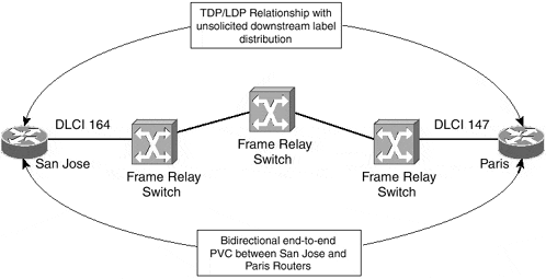
Using these VCs, you can establish MPLS forwarding and label distribution between two endpoint devices in exactly the same way as over any other type of interface that operates in Frame-mode. This means that the label distribution across the interface is unsolicited downstream with independent label control. Figure 4-1 provides an example of this type of connectivity.
Figure 4-1. MPLS Connectivity Across Frame Relay PVCs

Figure 4-1 illustrates two routers connected across a Frame Relay network. If you concentrate on the San Jose router, you can see that it addresses the VC using a Data Link Connection Identifier (DLCI) of 164 and uses this VC to exchange routing protocol information and to learn and distribute MPLS label forwarding information. From this router's perspective, any routes learned from its routing protocol neighbor across this VC (Paris in this case) have a next-hop forwarding address pointing to the Paris router.
When the San Jose router builds its LFIB, it uses the labels that it received across its TDP/LDP session with the Paris router to forward traffic to any FECs that it determines are reachable via the Paris router. You can see the relevant configuration of the San Jose router in Example 4-1.
Example 4-1 MPLS Across Frame Relay Router Configuration
hostname San Jose

!

interface serial 1/0

 description ** interface to Paris

 no ip address

 encapsulation frame-relay

!

interface Serial0/1.1 point-to-point

 ip address 146.4.1.18 255.255.255.252

 tag-switching ip

 frame-relay interface-dlci 164
To confirm the TDP relationship between the two routers, use the show tag-switching tdp neighbor command, as shown in Example 4-2. This command confirms that your TDP session is established across the Frame Relay interface and that unsolicited downstream label distribution is in effect.
Example 4-2 Confirmation of TDP Relationship Between Two LSRs Across Frame Relay
San Jose# show tag-switching tdp neighbor

Peer TDP Ident: 194.22.15.1:0; Local TDP Ident 194.22.15.2:0

     TCP connection: 194.22.15.1.711 ? 194.22.15.2.11363

     State: Oper; PIEs sent/rcvd: 124/123; ; Downstream

     Up time: 01:43:37

     TDP discovery sources:

      Serial0/1.1

     Addresses bound to peer TDP Ident:

      146.4.1.17    196.7.25.1      194.22.15.1    10.2.1.13
There are two ways to encapsulate IP packets across a Cisco Systems, Inc., implementation of Frame Relay. The first is to use Cisco encapsulation (the default) and the second is to use RFC 1490 (IETF) encapsulation. MPLS forwarding and control functions across either encapsulation. Figure 4-2 shows the two encapsulation methods and how the MPLS information is added to the frame.
Figure 4-2. MPLS Encapsulation Across Frame Relay


