Central Services Topology
A second very common topology that must be implemented with MPLS/VPN technology is the central services VPN. In this topology, the client sites can access services on central servers located at one or more central sites, but they cannot communicate with each other. A number of services can be implemented with this topology, including these:
Application hosting, in which a service provider provides access to applications residing on common servers. Application hosting can also include traditional service provider services such as hosted web sites or e-mail access.
Access to shared equipment, including dial-in pools or voice gateways.
Other value-added services, such as outsourced management of customer routers.
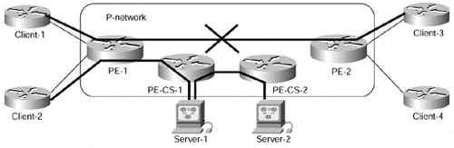
The connectivity requirements of all these services are summarized in Figure 11-3.
Figure 11-3. Connectivity Requirements of Central Services Topology
The MPLS/VPN design of the central services topology is easily inherited from the connectivity requirements. The following facts about VRFs and route distinguishers that need to be configured can be easily inferred from the requirements:
The client sites will not communicate?every client site needs to be placed in a separate VRF.
Every client site should use a different route distinguisher to prevent route conflict between the client sites.
Note
If all the client sites were on a single PE-router, they would need different route distinguishers because each VRF needs a unique route distinguisher. Because of several implementation issues, a similar rule also applies to VRFs configured on several PE-routers. In any case, the rules for the network designer are quite simple: If you want to use different VRFs (and thus different RD values) on a single PE-router, you should use different RD values even when deploying the topology across a number of PE-routers.
The server sites will freely communicate. They can be placed in the same VRF or, if connected to different PE-routers, can use the same route distinguisher.
Based on connectivity requirements, the route import and export procedures should be as follows:
Server sites will freely communicate. All routes from the server VRF must be exported with a route target (let's name it Server_RT) that is used as the import route target for other server VRFs.
Client sites will reach server sites. Importing routes with Server_RT into client VRFs will achieve this goal.
Server sites will reach client sites. All client routes will be exported with a common route target (let's call it Client_RT) and will be imported into server VRFs based on this route target.
Client sites will not communicate. Routes exported with Client_RT will not be imported into client VRFs.
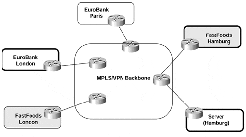
With these design rules in hand, it's easy to deploy a central services VPN solution. Let's assume that the EuroBank location in London and the FastFoods location in Hamburg need to access a common server located in Hamburg, as shown in Figure 11-4.
Figure 11-4. Central Services in SuperCom Network
The EuroBank site and the FastFoods site are already in different VRFs with unique route distinguishers (because of their intranet VPN connectivity requirements), and we can reuse those VRFs as client VRFs to provide access to the common server. A new server VRF must be configured in Hamburg, as shown in Example 11-1.
Example 11-1 Server VRF Configuration on Hamburg PE-router
ip vrf Server_HAM

  rd 1234:713

  route-target both 1234:710   ! Server_RT

  route-target import 1234:711 ! Client_RT
Additionally, Server_RT must be configured as the import route target in client VRFs, and Client_RT must be configured as the export route target in the same VRFs, as shown in Example 11-2.
Note
These two steps complete the core MPLS/VPN configuration of central services VPN. Additional steps not covered in this section are needed, including interface configuration, routing protocol configuration, and redistribution from VRF routing protocol into MP-BGP.
Example 11-2 Client VRF Configuration on Hamburg and London PE-routers
Hamburg#

ip vrf FastFoods_HAM

  rd 1234:18

  route-target import 1234:710  ! Server_RT

  route-target export 1234:711  ! Client_RT


London#

ip vrf EuroBank_LON

  rd 1234:17

  route-target import 1234:710  ! Server_RT

  route-target export 1234:711  ! Client_RT


