Advertisement of Routes Across the Backbone
To provide a virtual private network service based on the MPLS architecture, we have seen that our backbone infrastructure is required to service VPN client sites in various locations. It must be capable of propagating routing information from these clients across the backbone for advertisement to other members of the VPN. Our description has shown that to achieve this fundamental requirement, one of the necessary tools is MP-iBGP between PE-routers; this is an integral part of the MPLS/VPN architecture.
The implications of this requirement are quite apparent. It is clear that a full mesh of MP-iBGP sessions will be required, and as the number of VPN clients and PE-routers increases, so will the number of MP-iBGP sessions across the backbone. This is clearly an administrative nightmare. We must also consider that the service provider backbone may be required to carry normal BGP traffic so that non-VPN clients that require Internet access can be provided for.
So as we consider the scalability of our network design, we must keep in mind that the number of BGP sessions between PE-routers could become quite large. This means that it may be necessary to employ techniques that can help cut down on the number of sessions that are required and also to manage the distribution of routing information across the network so that we propagate information only to parts of the network where it is necessary.
The actual number of BGP sessions that a BGP speaker should service depends on many factors, primarily the amount of memory within the router and the speed of the CPU. It is difficult to predict exactly how many of these sessions would constitute a maximum, and indeed you would not want to deploy a solution that used this maximum limit. Therefore, published guidelines suggest that a BGP speaker should not service more than 100 BGP sessions, and techniques should be deployed to reduce the amount of BGP sessions that are required. Two main techniques exist within BGP to reduce the number of sessions that are required between PE-routers, although these are not the only ones that may be used. These techniques are using route reflectors and using confederations, and both may be deployed within an MPLS/VPN topology.
BGP for VPN-IPv4 and IPv4 Routing Information
Before we consider the mechanisms that help us to control the scalability of the BGP session requirement, we must understand what type of routing information will be needed within the core of the network and at the edges. We have already discussed how the introduction of MPLS can be used to remove BGP information from our core routers and that label switching can be used based on the BGP next-hop address of any external routes. Although this helps the service provider scale the backbone, it does not mean that BGP information is no longer required by the customers of the service provider.
In the case of customers that belong to the MPLS/VPN service, we know that we can carry their routing information within MP-iBGP updates. But we may also want to carry IPv4 routing information across the backbone so that the global routing tables of the PE-routers are populated. Without this information on the PE-routers, we would not be able to provide full or partial Internet routing information to VPN or non-VPN customers unless we adopted advanced BGP mechanisms, such as eBGP multihop, in combination with central BGP route servers and default routes in the service provider backbone.
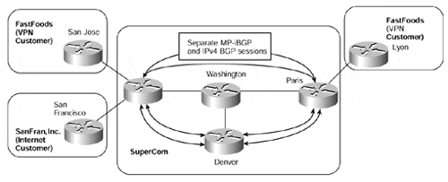
So in some cases, we need to provide BGP sessions that will carry VPN-IPv4 routes for the VPN customers and IPv4 routes for Internet customers. We could achieve this by configuring separate BGP sessions, one for the IPv4 routes and the other for the VPN-IPv4 routes. An example of this method can be seen in Figure 12-4. The relevant BGP session configurations for PE-routers San Jose and Paris are shown in Example 12-3, and output showing the relevant BGP sessions is shown within Example 12-4.
Figure 12-4. Multiple BGP Sessions Between PE-routers

Example 12-3 Multiple BGP Sessions Between PE-routers
hostname San Jose

!

interface loopback 0

 ip address 194.22.15.2 255.255.255.255

!

interface loopback 1

 ip address 194.22.16.2 255.255.255.255

!

router bgp 1

 no bgp default ipv4-unicast

 neighbor 194.22.15.1 remote-as 1

 neighbor 194.22.15.1 update-source Loopback0

 neighbor 194.22.15.1 activate

 neighbor 194.22.16.1 remote-as 1

 neighbor 194.22.16.1 update-source Loopback1

 !

 address-family vpnv4

  neighbor 194.22.16.1 activate

  neighbor 194.22.16.1 send-community extended

 exit-address-family


hostname Paris

!

interface loopback 0

 ip address 194.22.15.1 255.255.255.255

!

interface loopback 1

 ip address 194.22.16.1 255.255.255.255

!

router bgp 1

 no bgp default ipv4-unicast

 neighbor 194.22.15.2 remote-as 1

 neighbor 194.22.15.2 update-source loopback 0

 neighbor 194.22.15.2 activate

 neighbor 194.22.16.2 remote-as 1

 neighbor 194.22.16.2 update-source loopback 1

!

address-family vpnv4

 neighbor 194.22.16.2 activate

 neighbor 194.22.16.2 send-community extended

exit-address-family
Example 12-4 Multiple BGP Sessions?show ip bgp neighbor Output
San Jose# show ip bgp neighbor 194.22.15.1

BGP neighbor is 194.22.15.1,  remote AS 1, internal link

  BGP version 4, remote router ID 197.1.1.1

  BGP state = Established, up for 00:08:17

  Last read 00:00:17, hold time is 180, keepalive interval is 60

  seconds

  Neighbor capabilities:

    Route refresh: advertised and received

    Address family IPv4 Unicast: advertised and received

  Received 11 messages, 0 notifications, 0 in queue

  Sent 11 messages, 0 notifications, 0 in queue

  Route refresh request: received 0, sent 0

  Minimum time between advertisement runs is 5 seconds


 For address family: IPv4 Unicast

  BGP table version 1, neighbor version 1

  Index 1, Offset 0, Mask 0x2

  0 accepted prefixes consume 0 bytes

  Prefix advertised 0, suppressed 0, withdrawn 0


San Jose# show ip bgp neighbor 194.22.16.1

BGP neighbor is 194.22.16.1,  remote AS 1, internal link

  BGP version 4, remote router ID 197.1.1.1

  BGP state = Established, up for 00:08:12

  Last read 00:00:12, hold time is 180, keepalive interval is 60

  seconds

  Neighbor capabilities:

    Route refresh: advertised and received

    Address family VPNv4 Unicast: advertised and received

  Received 11 messages, 0 notifications, 0 in queue

  Sent 11 messages, 0 notifications, 0 in queue

  Route refresh request: received 0, sent 0

  Minimum time between advertisement runs is 5 seconds


 For address family: VPNv4 Unicast

  BGP table version 1, neighbor version 1

  Index 1, Offset 0, Mask 0x2

  0 accepted prefixes consume 0 bytes

  Prefix advertised 0, suppressed 0, withdrawn 0
Although the example shown in Figure 12-4 allows us to provide our desired functionality (because we are advertising VPN routes between PE-routers across MP-iBGP sessions anyway), it would be far better if we could just use these sessions for our IPv4 routes as well. Therefore, it is no surprise that MP-iBGP sessions are capable of carrying both VPN-IPv4 addresses and IPv4 addresses between PE-routers. This is controlled by the use of address families within the BGP configuration, which we discussed in Chapter 9, "MPLS/VPN Architecture Operation." A revamped configuration for PE San Jose from Figure 12-4 can be seen in Example 12-5.
Example 12-5 MP-iBGP for VPN-IPv4 and IPv4 Route Propagation
hostname San Jose

!

interface loopback 0

 ip address 194.22.15.2 255.255.255.255

!

router bgp 1


 neighbor 194.22.15.1 remote-as 1

 neighbor 194.22.15.1 update-source Loopback0


!

 address-family vpnv4

  neighbor 194.22.15.1 activate

  neighbor 194.22.15.1 send-community extended

 exit-address-family
Note
If the same session is used for both IPv4 and VPN-IPv4 address families, then the no bgp default ipv4-unicast command is not required. This means that the IPv4 session need not be manually activated anymore, although this is still required to allow the VPN-IPv4 session to come active.
Example 12-6 shows that only one BGP session now exists between PE-routers San Jose and Paris, and that this session carries both IPv4 unicast and VPN-IPv4 unicast routes.
Example 12-6 MP-iBGP Session with Two Address Families
San Jose# show ip bgp neighbor 194.22.15.1

BGP neighbor is 194.22.15.1,  remote AS 1, internal link

  BGP version 4, remote router ID 197.1.1.1

  BGP state = Established, up for 00:00:05

  Last read 00:00:04, hold time is 180, keepalive interval is 60

  seconds

  Neighbor capabilities:

    Route refresh: advertised and received

    Address family IPv4 Unicast: advertised and received

    Address family VPNv4 Unicast: advertised and received

  Received 20 messages, 0 notifications, 0 in queue

  Sent 20 messages, 0 notifications, 0 in queue

  Route refresh request: received 0, sent 0

  Minimum time between advertisement runs is 5 seconds


 For address family: IPv4 Unicast

  BGP table version 1, neighbor version 1

  Index 1, Offset 0, Mask 0x2

  0 accepted prefixes consume 0 bytes

  Prefix advertised 0, suppressed 0, withdrawn 0


 For address family: VPNv4 Unicast

  BGP table version 1, neighbor version 0

  Index 1, Offset 0, Mask 0x2

  0 accepted prefixes consume 0 bytes

  Prefix advertised 0, suppressed 0, withdrawn 0
Full Mesh of MP-iBGP Between PE-routers
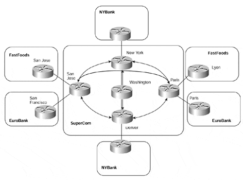
Now that it is clear that we can carry both VPN-IPv4 and IPv4 addresses within the same MP-iBGP sessions, we need to decide how these peering sessions between PE-routers should be deployed. The simplest way to achieve this may be to just configure a full mesh of MP-iBGP sessions between PE-routers and rely on the filtering features that we discussed in Chapter 9, such as automatic route filtering. This option can be seen in Figure 12-5.
In the topology shown in Figure 12-5, each PE-router has an MP-iBGP session with every other PE-router within the backbone. You can see that as the number of PE-routers increases, we start to encounter scaling and management problems. This is because the number of MP-iBGP sessions between the PE-routers increases at the rate of one new session per existing PE-router, for each new PE-router introduced into the network. Even more troublesome, every time you add a new router into the service provider backbone, a new BGP neighbor must be inserted into the core BGP configuration on all BGP-speaking routers in the service provider backbone to retain the full-mesh topology.
In some network deployments, this may not be an issue because the size of the infrastructure may be quite small, and this type of topology might be appropriate. However, in most cases, this type of configuration should be avoided unless the expansion of the network is known to be minimal.
Figure 12-5. Full Mesh of MP-iBGP Between PE-routers

One further point of interest can be deduced from Figure 12-5: A full mesh of MP-iBGP sessions between PE-routers may not actually be required because of the nature of the distribution of VPN routing information. We have already discussed that the MPLS/VPN architecture requires that PE-routers learn routes only for VPNs that are directly connected to them. If we take a look once more at our example, we can see that the PE-routers in New York and Denver have only customers that belong to the NYBank VPN, and PE-routers San Jose and Paris have only customers that belong to the FastFoods and EuroBank VPNs. This means that PE-routers New York and Denver do not need to receive any information about the FastFoods or EuroBank VPNs, and the San Jose and Paris routers do not need to receive any information about the NYBank VPN.
Separation of MP-iBGP Sessions Between PE-routers
To help alleviate the need of a full mesh of MP-iBGP sessions between PE-routers, and to make sure that PE-routers receive only routes that are applicable to the VPNs that they service, we can partition each of the PE-routers into separate mini MP-iBGP clusters. Each of these clusters is still required to run a full MP-iBGP mesh, but the size of each mesh can be considerably reduced. The actual session requirement is based on which PE-routers need to send routing information to which other PE-routers.
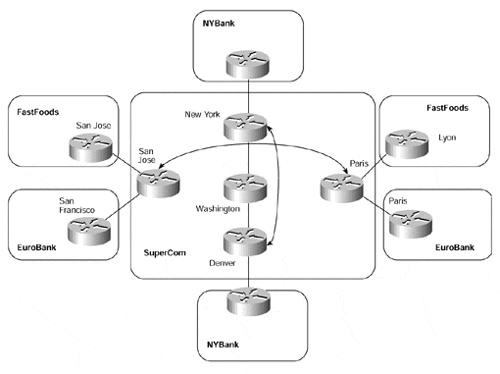
Figure 12-6 provides an example of this and shows that our previous example has now been changed. MP-iBGP sessions now are provisioned only between PE-routers that hold customers that require the same VPN routing information.
Figure 12-6. Separation of MP-iBGP Sessions Between PE-routers

Although this solution provides the capability to separate the full-mesh MP-iBGP requirement, it does not provide a scalable solution in terms of network growth, and it eventually suffers from the same drawbacks as the previous solution. It also introduces additional complexity in the network design and deployment phases because the MP-iBGP sessions must be carefully planned before introduction of a new customer or site.
As seen in Figure 12-6, as the network grows, the number of MP-iBGP sessions grows, albeit in separate full-mesh clusters. If a further PE-router were added to this sample topology, and if this required routes for the FastFoods VPN, then a further MP-iBGP session would need to be configured to this new PE-router from both the San Jose and Paris routers.
It should be clear by now that a different mechanism is required to help scale the topology. This mechanism is provided through the use of BGP route reflectors or confederations.


