Internet Access?Static Default Routing
In our sample topology, certain customers, such as the EuroBank VPN customer, want to obtain direct Internet access from a VPN. These customers have no requirement to receive full Internet routing, so a static default route pointing to a global next-hop address can be placed within the EuroBank VRF. This static route should point to the router that acts as the Internet gateway?in this case, the SuperCom New York router.
Note
Whenever a default route is placed into the VRF and this default route points to a next-hop address contained within the global routing table, any packets that use this default route will leave the VPN space and will be routed based on the global routing table at the next-hop router. This feature allows "leaking" of VPN packets into the global address space.
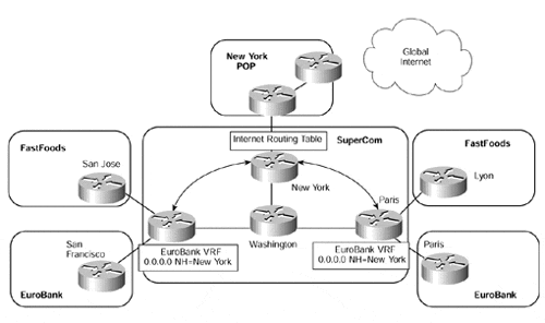
By placing a static default route within the EuroBank VRF, any packets that do not match any of the routes contained within the VRF will be sent to the SuperCom New York router, which provides the Internet gateway facility. This connectivity is illustrated in Figure 12-21.
Figure 12-21. Internet Connectivity?Static Default Route

The next-hop address for the static default route should point to the interface from where the Internet routes are learned. You might be tempted to use the loopback interface address of the Internet gateway because this type of interface will never be unavailable unless the Internet gateway itself is not reachable. However, the problem with this approach is that the Internet gateway itself may be reachable, but its interface to the Internet may be down. This could cause suboptimal routing in the best case, but potentially black-hole traffic in the worst case.
In the example shown in Figure 12-21, a static default route has been configured into the EuroBank VRF on the San Jose and Paris routers, and this points to the interface of the New York router that provides the Internet gateway. This interface address must be present within the global routing table so that label switching of the packets between the PE and Internet gateway routers can occur. This means that the Internet gateway router must advertise its Internet interface address within the IGP that runs across the backbone.
Note
In the context of the MPLS/VPN architecture, the global routing table can be defined as the table that contains any routes other than VPN routes. These will typically include Internet routes.
When packets from a VPN customer reach the Internet gateway, they must be treated as belonging to the global routing table rather than a VRF, whether labeled or not. This means that the interface used to access the Internet must not be within the VPN?it must belong to the global routing table. If it belonged to the VPN, then when packets from a VPN customer reached the Internet gateway, a lookup within the VRF would occur rather than within the global routing table, which is where the Internet routes reside, and connectivity would not be achieved.
Note
It is possible to associate the Internet routing table with a VRF so that all Internet routes reside within the VRF rather than the global routing table. In this case, the interface that connects to the Internet on the Internet gateway could reside within the VRF. However, this design is strongly discouraged if you propagate full Internet routing in your network (unless you use special techniques detailed later in this chapter) because the number of routes inserted into the Internet VRF would be very large. To make matters worse, if you decide to design Internet access through an overlapping VPN structure, each customer VRF (with its unique route distinguisher) would cause the BGP process to generate another copy of all the Internet routes within the VPN-IPv4 BGP table.
In a normal routing scenario, the configuration of a static route that points to an unreachable next-hop address would not be valid. This is actually the situation that we have in the MPLS/VPN model: The next-hop of the static route is not present within the VRF.
Note
This situation is the case for all VPN routes learned through MP-iBGP in any VRF. The MP-iBGP next-hop address is always resolved in the global routing table, not within the VRF.
Because there is no redistribution between IPv4 and VPN-IPv4 routes, a method is needed to allow the PE-router to resolve the next-hop address for the Internet gateway from within the VRF. This is achieved through the use of the global keyword within the static default route configuration. The global keyword specifies that the next-hop address of the static route is resolved within the global routing table, not within the VRF. Example 12-10 provides the format of the command; the configuration for the San Jose router in Figure 12-21 can be seen in Example 12-11.
Example 12-10 Static Default Route Configuration Command Syntax
ip route vrf vrfname 0.0.0.0 0.0.0.0 Internet_GW_next-hop global
Example 12-11 Static Default Route?San Jose PE Configuration
hostname San Jose

!

ip route vrf EuroBank 0.0.0.0 0.0.0.0 197.22.15.6 global
Note
The label stack for the default route will contain only one label, and this will be the one assigned to the IGP route of the Internet gateway next-hop address.
The configuration of the static default route into the VRF provides an outbound route toward the Internet for members of the VPN, but what about the return path? Connectivity can be achieved only if two-way routing can occur. This means that each of the customer IP subnets (advertised by the customer as VPN routes to the PE-routers) that are used as source addresses for Internet access must be advertised through the global BGP-4 process toward the Internet. However, BGP-4 will not advertise any routes that were not learned from a BGP peer or, if sourced locally, are not contained within the global routing table of the advertising router.
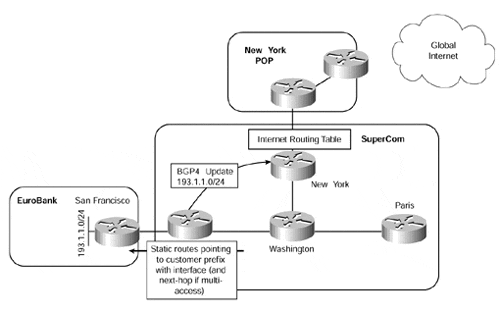
We have already seen that the VPN routes are kept separate from the global routing table and are not available to be advertised through BGP-4. The easiest solution to make these routes available in the global routing table is to configure further (global) static routes so that the VPN subnets appear within the global routing table as well as the VRF. This would make them available for advertisement via BGP-4. These static routes must point to an interface, with a next-hop address specified if the outbound interface is multiaccess (such as Ethernet). Then either these routes can be redistributed into BGP, or the network command can be used within the BGP process. If redistribution is used, a route map can be utilized to specify which addresses to advertise.
A next-hop address for these static routes can be specified even though the next-hop is not present in the global routing table. In normal routing, this would not be possible because the next-hop would not be within the routing table and therefore would never be validated. However, within the MPLS/VPN environment, this type of configuration is valid. Figure 12-22 provides an example of this type of topology, with the necessary configuration for the San Jose PE-router shown in Example 12-12. Example 12-12 also shows that the static route is contained within the global routing table of the PE-router, even though the next-hop and outbound interface addresses are not present (they belong to a VRF).
Figure 12-22. Advertisement of VPN Routes into the Global BGP-4 Process

Example 12-12 Static Route Configuration for BGP-4 Advertisement of VPN Routes
hostname San Jose

!


! static route pointing to EuroBank 193.1.1.0/24 prefix

!

ip route 193.1.1.0 255.255.255.0 ethernet6/0 10.2.1.25


San Jose# show ip route

Codes: C - connected, S - static, I - IGRP, R - RIP, M - mobile, B - BGP

       D - EIGRP, EX - EIGRP external, O - OSPF, IA - OSPF inter area

       N1 - OSPF NSSA external type 1, N2 - OSPF NSSA external type 2

       E1 - OSPF external type 1, E2 - OSPF external type 2, E - EGP

       i - IS-IS, L1 - IS-IS level-1, L2 - IS-IS level-2, ia - IS-IS inter area

       * - candidate default, U - per-user static route, o - ODR

       P - periodic downloaded static route


Gateway of last resort is not set


     1.0.0.0/32 is subnetted, 1 subnets

S       193.1.1.0/24 [1/0] via 10.2.1.25, Ethernet6/0
If the service provider has multiple Internet exit points, then static routes for different VPN customers can be configured by pointing the next-hop address to one of the multiple Internet exit points. It may also be useful to change the autonomous system number within the AS_PATH when a VPN customer static route is redistributed into BGP so that the first autonomous system number in the AS_PATH is not the MPLS/VPN provider's, but the customer's. Example 12-13 shows a configuration that would cause the 193.1.1.0/24 prefix as shown in Example 12-12 to be advertised with an autonomous system number of 200 rather than the service provider's autonomous system number.
Example 12-13 Setting the AS Number During Redistribution into BGP
router bgp 100

 redistribute static set-as-path-EuroBank-from-tag

!

route-map set-as-path-EuroBank-from-tag

 set aspath tag

!

ip route 193.1.1.0 255.255.255.0 ethernet6/0 10.2.1.25 tag 200


