MPLS/VPN Hub-and-spoke Topology
In certain circumstances, it may be desirable to use a hub-and-spoke topology so that all spoke sites send all their traffic toward a central site location. This may be because certain central site services for a particular VPN, such as Internet access, firewalls, server farms, and so on, are housed within the hub site. Or it may be because this particular VPN customer requires that all connectivity between its sites be via the central site.
In either case, it is necessary to define a hub site that contains full routing knowledge of all spoke sites that belong to the same VPN. All traffic from the spoke sites, destined either for the central site services or for intersite connectivity, will flow via the central hub site. With this type of topology, the spoke sites export their routes to the hub site, and then the hub site re-exports the spoke site routes through a second interface (either physical or logical) using a different route target so that other spoke sites can import the routes. This causes the hub site to become a transit point for interspoke connectivity.
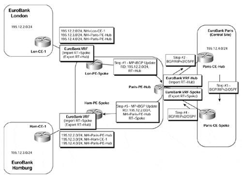
An example of this type of topology is shown in Figure 11-5. This figure shows two spoke sites, EuroBank London and EuroBank Hamburg, that do not have direct connectivity but that can reach each other by sending traffic via the EuroBank Paris central site.
Figure 11-5. Hub-and-spoke Connectivity Model

For simplicity, the relevant route targets have been given names rather than numerical values. We can see in Figure 11-5 that the EuroBank London site advertises its local prefixes, an example of which is 195.12.2.0/24, and these are placed into the EuroBank VRF on the Lon-PE-Spoke PE-router. To achieve the desired connectivity, the following steps can be taken:
The Lon-PE-Spoke PE-router exports all the routes from the EuroBank VRF using a route target value of Hub.
The hub PE-router (Paris-PE-Hub, within the figure) is configured to import the Hubroute target into one of its VRFs (defined as VRF-Hub in Figure 11-5). This VRF interface attaches to the EuroBank central site and forwards all routes that are learned from the spoke sites to the CE-router (Paris-CE3-Hub), which is located within the central site.
The Paris-CE3-Hub CE-router advertises these routes across the central site.
The routes are eventually advertised back to the Paris-PE-Hub PE-router across a separate interface.
The Paris-PE-Hub PE-router then advertises the routes back into the MPLS/VPN backbone with a route target value of Spoke.
Each of the spoke PE-routers (Lon-PE-Spoke and Ham-PE-Spoke) is configured to import any routes with a route target value of Spoke into the EuroBank VRF. This means that the next-hop address for all the spoke sites, as seen by other spoke sites, is via the central site Paris-PE-Hub PE-router.
The simplest way to configure this type of connectivity would be to assign the same route distinguisher to each spoke site VRF because the spoke sites do not exchange routing information directly with each other and do not import each other's route targets. As briefly discussed in Chapter 9, this is possible when the spoke sites are not connected to the same PE-router as the hub site. This is because of the automatic VPN-IPv4 route filtering feature (also discussed in Chapter 9), which filters any routes that contain a route target that is not configured to be imported into any VRFs on the PE-router. In the case of a distributed hub-and-spoke model, such as the one shown in Figure 11-5, everything works fine because the spoke PE-routers are not configured to import the route target with a value of Spoke. However, if the hub-and-spoke sites are connected to the same PE-router, then it is essential to assign a different route distinguisher per spoke site VRF; otherwise, the automatic route filtering feature will not filter the routes with a route target value of Spoke, and essential routing information could potentially be lost.
The loss of routing information can be explained through the MPLS/VPN architecture and also through how the BGP selection process is executed within an MPLS/VPN environment. Architecturally, two or more VRFs may use the same route distinguisher if these VRFs are used by sites belonging to the same VPN and share exactly the same routing information. This is not the case with the hub-and-spoke topology because the hub site imports different routes from the spoke sites.
The BGP selection process applies to all routes that must be imported into the same VRF, plus all routes that have the same route distinguisher as this VRF. When the selection process is finished, only the best routes are effectively imported. In the case of the hub-and-spoke topology, if the same route distinguisher is used for each spoke site, this could result in a "best" route that is not imported into the VRF. This is because, if all spoke VRFs have the same route distinguisher, then each PE-router will include in the selection process not only the routes coming from the hub site, but also the routes coming from the other spoke sites (which are not configured to be imported). Automatic route filtering will prevent this if the topology is distributed, but it will not help if the hub-and-spoke sites are connected through the same PE-router.
Note
It is also worth noting that if the same route distinguisher is used on every PE-router for a particular VPN, then the topology is somewhat restricted because it requires that all spokes connected to a particular PE-router for a particular VPN use the same VRF. This is because each VRF on a PE-router must have a unique route distinguisher. This means that all spokes for a particular VPN would need to share the exact same routing information.
Deployment of the AllowAS-in Feature
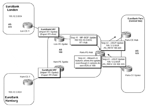
Readers that are familiar with the BGP may notice a fundamental problem with the description of the hub-and-spoke topology operation given so far. This problem stems from the fact that the BGP protocol states that a BGP speaker should ignore a received update that contains within its AS_PATH attribute its own autonomous system number (ASN). If we refer back to Figure 11-5, we can see that this is in fact the case when the hub-and-spoke topology is deployed. There, the Paris-PE-Hub PE-router will advertise routes from the VRF named VRF-Hub toward the EuroBank Paris central site with the MPLS/VPN backbone ASN contained within the AS_PATH. These routes will be readvertised back toward the MPLS/VPN backbone, to be received by the Paris-PE-Hub PE-router into the VRF named VRF-spoke.
Note
This issue will arise only if BGP is used between the PE- and CE-routers at the hub site and if pervasive BGP is used within the site.
To overcome this issue so that the use of the hub-and-spoke topology becomes possible, a new feature known as AllowAS-in has been introduced so that the receiving PE-router disables the AS_PATH check for routes learned from the central site location. The use of this feature is illustrated in Figure 11-6.
Figure 11-6. Deployment of the AllowAS-in Feature

Note
The hub-and-spoke topology may also require the deployment of the Site of Origin (SOO) attribute. This attribute was discussed in detail in Chapter 9.
The AllowAS-in feature is implemented using the command shown in Example 11-3,with the relevant configuration of the Paris-PE-Hub router shown in Example 11-4:
Example 11-3 Configuration of the AllowAS-in Feature
neighbor x.x.x.x allowas-in ASN_limit
Note
Routing loops are avoided by setting a limit of the number of occurrences of the MPLS/VPN backbone autonomous system number in the update from the VPN hub site. This is controlled through use of the ASN_limit parameter within the neighbor command.
Example 11-4 BGP Configuration with AllowAS-in Example
router bgp 100

!

 address-family ipv4 vrf VRF-Spoke

  neighbor 195.12.4.5 remote-as 123

  neighbor 195.12.4.5 activate

  neighbor 195.12.4.5 allowas-in 2

 exit-address-family

!
Note
If it is possible to either advertise an aggregate from the hub site that covers the address range used by all spoke sites, or advertise a default route, then the use of the AllowAS-in feature is not necessary.


