Overlay and Peer-to-peer VPN Model
Two VPN implementation models have gained widespread use:
The overlay model, where the service provider provides emulated leased lines to the customer.
The peer-to-peer model, where the service provider and the customer exchange Layer 3 routing information and the provider relays the data between the customer sites on the optimum path between the sites and without the customer's involvement.
Note
One might argue that the case where the customer and the provider use the same Layer 2 technology (for example, Frame Relay or ATM switches) also constitutes a peer-to-peer model, but because we focus on Layer 3 VPN services here, we will not consider this scenario. Similarly, a humorous person might call a leased line service a Layer 1 peer-to-peer model.
Overlay VPN Model
The overlay VPN model is the easiest to understand because it provides very clear separation between the customer's and the service provider's responsibilities:
The service provider provides the customer with a set of emulated leased lines. These leased lines are called VCs, which can be either constantly available (PVCs) or established on demand (SVCs). Figure 7-5 shows the topology of a sample overlay VPN and the VCs used in it.
Figure 7-5. Sample Overlay VPN Network
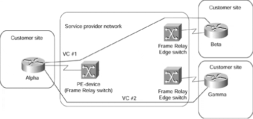
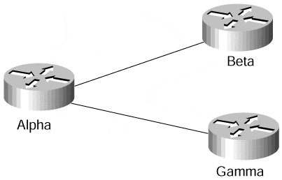
The customer establishes router-to-router communication between the Customer Premises Equipment (CPE) devices over the VCs provisioned by the service provider. The routing protocol data is always exchanged between the customer devices, and the service provider has no knowledge of the internal structure of the customer network. Figure 7-6 shows the routing topology of the VPN network in Figure 7-5.
Figure 7-6. Routing in Sample Overlay VPN Network
The QoS guarantees in the overlay VPN model usually are expressed in terms of bandwidth guaranteed on a certain VC (Committed Information Rate or CIR) and maximum bandwidth available on a certain VC (Peak Information Rate or PIR). The committed bandwidth guarantee usually is provided through the statistical nature of the Layer 2 service but depends on the overbooking strategy of the service provider. This means that the committed rate is not actually guaranteed although the provider can provision a Minimum Information Rate (MIR) that effectively is nailed up across the Layer 2 infrastructure.
Note
The committed bandwidth guarantee is also only a guarantee of the bandwidth between two points in the customer network. Without a full traffic matrix for all traffic classes, it's hard for the customer to engineer guarantees in most overlay networks. It's also hard to provide multiple classes of service because the service provider cannot differentiate the traffic in the middle of the network. Working around this by creating multiple connections (for example, Frame Relay PVCs) between the customer sites only increases the overall cost of the network.
Overlay VPN networks can be implemented with a number of switched WAN Layer 2 technologies, including X.25, Frame Relay, ATM, or SMDS. In the last years, overlay VPN networks also have been implemented with IP-over-IP tunneling, both in private IP backbones and over the public Internet. The two most commonly used IP-over-IP tunneling methods are Generic Route Encapsulation (GRE) tunneling and IP Security (IPSec) encryption.
Note
This book does not discuss the various Layer 2 and Layer 3 overlay VPN technologies in detail because they are covered well in other Cisco Press publications and are beyond the scope of this book. For more information on Layer 2 WAN technologies, please refer to Internetworking Technologies Handbook, Second Edition, from Cisco Press (ISBN 1-57870-102-3). For a description of IP-over-IP tunneling and IPSec encryption, please see RFC 1702 ? Generic Routing Encapsulation over IPv4 networks, RFC 2401 ? Security Architecture for the Internet Protocol, and Enhanced IP Services for Cisco Networks from Cisco Press (ISBN 1-57870-106-6).
Although it's relatively easy to understand and implement, the overlay VPN model nevertheless has a number of drawbacks:
It's well suited to non-redundant configurations with a few central sites and many remote sites, but becomes exceedingly hard to manage in a more meshed configuration (see also the section, "Typical VPN Network Topologies," later in this chapter for more details).
Proper provisioning of the VC capacities requires detailed knowledge of site-to-site traffic profiles, which are usually not readily available.
Last but not least, the overlay VPN model, when implemented with Layer 2 technologies, introduces another unnecessary layer of complexity into the New World Service Provider networks that are mostly IP-based, thus increasing the acquisition and operational costs of such a network.
Peer-to-peer VPN Model
The peer-to-peer VPN model was introduced a few years ago to alleviate the drawbacks of the overlay VPN model. In the peer-to-peer model, the Provider Edge (PE) device is a router (PE-router) that directly exchanges routing information with the CPE router. Figure 7-7 shows a sample peer-to-peer VPN, which is equivalent to the VPN in Figure 7-5.
Note
The Managed Network service offered by many service providers, where the service provider also manages the CPE devices, is not relevant to this discussion because it's only a repackaging of another service. The Managed Network provider concurrently assumes the role of the VPN service provider (providing the VPN infrastructure) and part of the VPN customer role (managing the CPE device).
Figure 7-7. Sample Peer-to-peer VPN
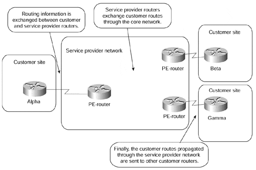
Note
Please note that this section describes the non-MPLS approach to peer-to-peer VPN as currently deployed by several large service providers and the complexities associated with it. The MPLS-based peer-to-peer VPN approach is described in the next chapter.
The peer-to-peer model provides a number of advantages over the traditional overlay model:
Routing (from the customer's perspective) becomes exceedingly simple, as the customer router exchanges routing information with only one (or a few) PE-router, whereas in the overlay VPN network, the number of neighbor routers can grow to a large number.
Routing between the customer sites is always optimal, as the provider routers know the customer's network topology and can thus establish optimum inter-site routing.
Bandwidth provisioning is simpler because the customer has to specify only the inbound and outbound bandwidths for each site (Committed Access Rate [CAR] and Committed Delivery Rate [CDR]) and not the exact site-to-site traffic profile.
The addition of a new site is simpler because the service provider provisions only an additional site and changes the configuration on the attached PE-router. Under the overlay VPN model, the service provider must provision a whole set of VCs leading from that site to other sites of the customer VPN.
Prior to an MPLS-based VPN implementation, two implementation options existed for the peer-to-peer VPN model:
The shared-router approach, where several VPN customers share the same PE-router.
The dedicated-router approach, where each VPN customer has dedicated PE-routers.
Shared-router Approach to Peer-to-peer VPN Model
In the shared-router approach, several customers can be connected to the same PE-router. Access lists have to be configured on every PE-CE interface on the PE-router to ensure isolation between VPN customers, to prevent a VPN customer from breaking into another VPN network, or to prevent a VPN customer from performing a denial-of-service attack on another VPN customer. Figure 7-8 illustrates a sample shared-router configuration.
Figure 7-8. Peer-to-peer VPN Model: Shared Router Configuration
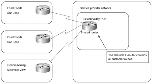
Let's assume that the customers shown in Figure 7-8 use the address space and routing protocols from Table 7-1.
|
Customer Name |
Address Space |
Routing Protocol |
|---|---|---|
|
FriedFoods (Customer #75) |
155.13.0.0/16 |
RIP |
|
GeneralMining (Customer #98) |
195.166.16.0/20 |
OSPF (area 3) |
To ensure the isolation between the customers, the configuration from Example 7-1 would have to be entered in the POP-router in Figure 7-8.
Example 7-1 POP-router Configuration
interface serial 0/0/1

 description FriedFoods ? San Jose Site

 ip address 153.13.254.1 255.255.255.252

! The IP address on WAN link is an address from Customer's address space

 ip access-group FriedFoods in

 ip access-group FriedFoods out

!

interface serial 0/0/2

 description FriedFoods ? Santa Clara Site

 ip address 153.13.254.5 255.255.255.252

 ip access-group FriedFoods in

 ip access-group FriedFoods out

!

interface serial 0/1/3

 description GeneralMining ? Mountain View Site

 ip address 195.166.31.17 255.255.255.252

 ip access-group GeneralMining in

 ip access-group GeneralMining out

!

router rip

 network 153.13.0.0

!

router ospf 1

 network 195.166.31.17 0.0.0.0 area 3

!

ip access-list FriedFoods

  permit ip 155.13.0.0 255.255.0.0 153.13.0.0 255.255.0.0

!

ip access-list GeneralMining

  permit ip 195.166.16.0 255.255.240.0 195.166.16.0 255.255.240.0
Dedicated-router Approach to Peer-to-peer Model
In the dedicated-router approach to the peer-to-peer model, every VPN customer has their own dedicated PE routers (as detailed in Figure 7-9) and, thus, has access only to the routes contained within the routing table of that PE router.
Figure 7-9. Peer-to-peer VPN Model: Dedicated Router Configuration
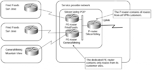
The dedicated-router model uses routing protocols to create per-VPN routing tables on PE routers. The routing tables on PE-routers contain only the routes advertised by the VPN customer connected to them, resulting in almost perfect isolation between the VPN customers (assuming that the IP source routing is disabled). The routing in the dedicated-router model can be implemented as follows:
Any routing protocol is run between the PE-router and the CE-router.
BGP is run between the PE-router and the P-router.
The PE-router redistributes routes received from the CE-router into BGP, marked with the customer ID (BGP community), and propagates the routes to the P-routers. P-routers thus contain all the routes from all VPN customers.
P-routers propagate only routes with the proper BGP community to the PE-routers. The PE-routers thus receive only the routes that originated from the CE-routers in their VPN.
Relevant parts of PE-router and P-router configuration for the Service Provider Point-of-Presence (POP) shown in Figure 7-9 (assuming the address space and the routing protocols from Table 7-1) can be found in Example 7-2 and Example 7-3.
Example 7-2 PE-router Configuration
hostname PE-router-FriedFoods

!

interface serial 0/0/1

 description FriedFoods ? San Jose Site

 ip address 153.13.254.1 255.255.255.252

!

interface serial 0/0/2

 description FriedFoods ? Santa Clara Site

 ip address 153.13.254.5 255.255.255.252

!

interface FastEthernet 2/0/0

 description Intra-POP LAN

 ip address 10.13.1.2 255.255.255.0

!

router rip

 network 153.13.254.1

 version 2

 redistribute bgp 111 subnets

!

router bgp 111

 no auto-summary

 redistribute rip route-map ToBGP-FriedFoods

 neighbor 10.13.1.1 remote-as 111

!

route-map ToBGP-FriedFoods permit 10

 set community 111:75
Example 7-3 P-router Configuration
hostname P-Router-Silicon-Valley-POP

!

interface FastEthernet 0/1/0

 description Intra-POP LAN

 ip address 10.13.1.1 255.255.255.0

!

router bgp 111

 neighbor 10.13.1.2 remote-as 111

 neighbor 10.13.1.2 route-reflector-client

 neighbor 10.13.1.2 route-map VPN-FriedFoods out

!

route-map VPN-FriedFoods permit 10

 match community-list 75

!

ip community-list 75 permit 111:75
Comparison of Peer-to-peer Models
As you easily can deduce from Example 7-1, the shared-router peer-to-peer model is very hard to maintain because it requires the deployment of potentially long and complex access lists on almost every router interface. The dedicated-router approach, although simpler to configure and maintain, becomes very expensive for the service provider when it tries to serve a large number of customers with geographically dispersed sites.
Both peer-to-peer models also share several common drawbacks that prevent their widespread usage:
All the customers share the same IP address space, preventing the customers from deploying private IP addresses according to RFC 1918. The customers must use either public IP addresses or private IP addresses allocated to them by the service provider.
The customers cannot insert the default route into their VPN. This limitation prevents certain routing optimizations and prevents the customers from getting Internet access from another service provider.
In addition to these two drawbacks, the shared-router model suffers from additional complexity when several customers use the routing protocols (RIP, RIPv2, BGP, and IS-IS) where multiple instances are not supported in Cisco IOS.


